Keysight Technologies PD1500A System Installation Manual
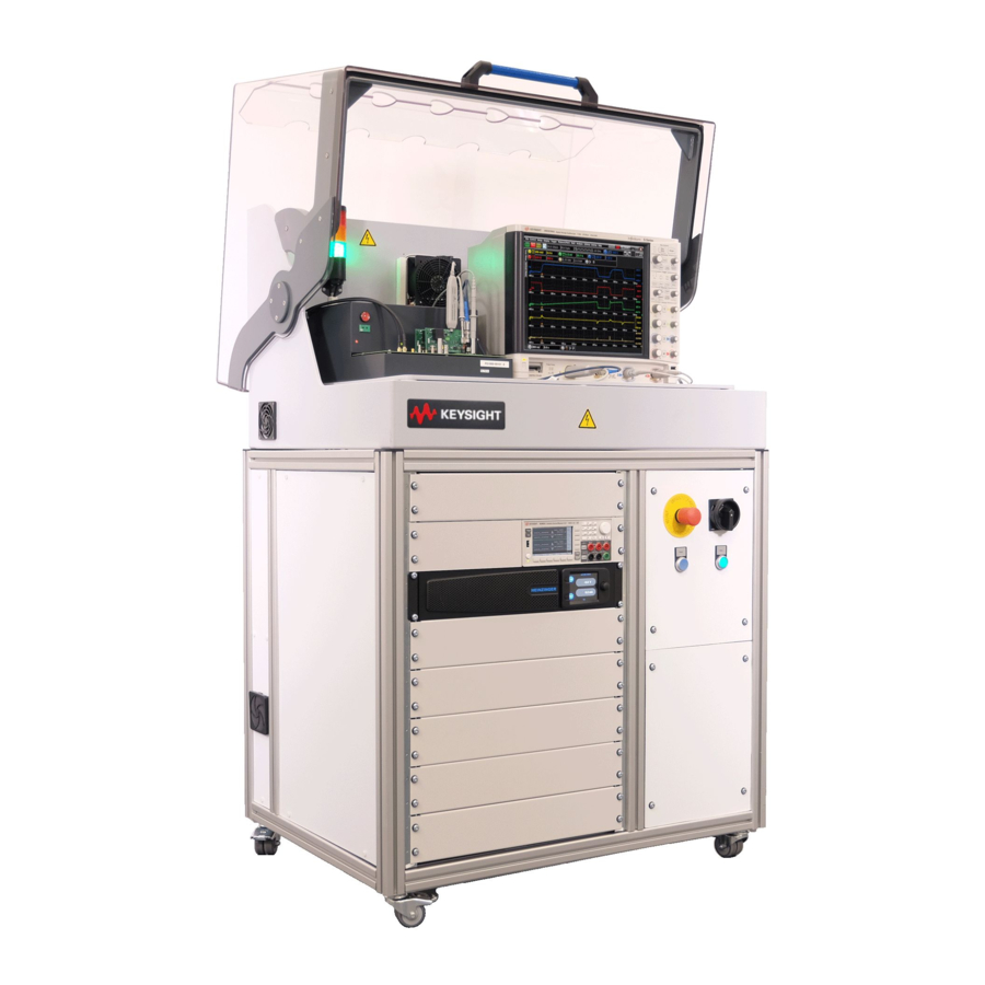
Double-pulse test rack and safety enclosure
Hide thumbs
Also See for PD1500A:
- Operation and maintenance (32 pages) ,
- Software manual (146 pages) ,
- Installation and use manual (93 pages)
Table of Contents
Advertisement
Quick Links
Keysight PD1500A
Double-Pulse Test Rack and
Safety Enclosure
Provides detailed information to install the Double-
Pulse Test Rack and Safety Enclosure at a customer
site. The Rack and Safety Enclosure is used with the
PD1500A Dynamic Power Device Analyzer/Double-
Pulse Tester.
System Installation
Guide
Advertisement
Chapters
Table of Contents

Related Manuals for Keysight Technologies PD1500A


Summary of Contents for Keysight Technologies PD1500A
- Page 1 Double-Pulse Test Rack and Safety Enclosure Provides detailed information to install the Double- Pulse Test Rack and Safety Enclosure at a customer site. The Rack and Safety Enclosure is used with the PD1500A Dynamic Power Device Analyzer/Double- Pulse Tester. System Installation Guide...
- Page 3 WITHOUT NOTICE, IN FUTURE EDI- without prior agreement and written con- www.keysight.com/find/PD1500A TIONS. FURTHER, TO THE MAXIMUM sent from Keysight Technologies, Inc. as EXTENT PERMITTED BY APPLICABLE (product-specific information and sup- governed by United States and interna- LAW, KEYSIGHT DISCLAIMS ALL WAR- port, software and documentation tional copyright laws.
- Page 4 Safety Information The following general safety precau- Do Not Operate Near Flammable Do Not Modify the Instrument Liquids tions must be observed during all Do not install substitute parts or per- phases of operation of these instru- Do not operate the instruments in the form any unauthorized modification to ments.
- Page 5 Safety and Regulatory Symbols A CAUTION denotes a hazard. It calls attention to an operating pro- cedure or practice that, if not cor- The CE marking is a registered trade- rectly performed or adhered to, R-R-Kst-SP19629 mark of the European Community (if could result in damage to the accompanied by a year, it is the year South Korean Certification (KC) mark.
- Page 6 Waste Electrical and German Portuguese Electronic Das Symbol der durchgestrichenen O símbolo da lata de lixo riscada indica Equipment (WEEE) Mülltonne auf Rädern weist darauf hin, que a necessidade da coleta seletiva dass eine getrennte Sammlung von dos resíduos de equipamentos eléctri- Elektro- und Elektronik-Altgeräten cos e electrónicos (REEE) é...
- Page 7 Failure to comply with these precautions or with specific warnings elsewhere in this manual may impair the protections provided by the system. In addition, it violates safety standards of design, manufacture, and intended use of the system. Keysight Technologies assumes no liability for customer’s failure to comply with these requirements.
- Page 8 • Instruments, probes or cables that appear damaged or defective should be made inoperative and secured against unintended operation until they can be repaired by qualified service personnel. Return the product to a Keysight Technologies sales or service office for service and repair to ensure that safety features are maintained.
-
Page 9: Table Of Contents
Contents 1 Site Preparation Customer Responsibilities ......... 16 Rack and Safety Enclosure Dimensions and Weight . - Page 10 Install the De-Embedding Transfer File on the Oscilloscope... . 68 6 PD1500A Double-Pulse Test Si/SiC AutoCalibration Initiate Calibration & Compensation Procedures ..... 70 Oscilloscope Probe Compensation .
- Page 11 Low Frequency Compensation for the 10076C and N2873A Probes ..71 Offset Compensation for the N2819A Differential Probe....72 Si/SiC System Calibration Procedure (Autocal) ......74 Requirements .
- Page 12 Keysight Double-Pulse Test System Installation Guide...
- Page 13 See “Customer Responsibilities” on page 16. This System Installation Guide provides step-by-step instructions to assemble and install the PD1500A Dynamic Power Device Analyzer/Double-Pulse Tester. Note that the PD1500A is part of the overall PD1000A Power Device Measurement System for Advanced Modeling. In this chapter:...
-
Page 14: Site Preparation
Site Preparation Customer Responsibilities Customer Responsibilities This System Installation Guide provides instructions for a Keysight-trained Application Engineer to install the Keysight PD1500A DPT System Rack and Safety Enclosure. page 20 Receive the Double-Pulse Test System (multiple shipping containers). See ... -
Page 15: Double-Pulse Test Rack And Safety Enclosure Location
Double-Pulse Test Rack and Safety Enclosure Location Site Preparation Double-Pulse Test Rack and Safety Enclosure Location The DPT Rack and Safety Enclosure is a free-standing rack with test instruments installed and a Safety Hood on top. It is the customer’s responsibility to consider the anticipated location and requirements to ensure safety and optimize access to test and control instrumentation. -
Page 16: Electrical And Environmental Requirements
A mains power cord, (8121-3445 for N. America and Japan, or 8121-3356 for all other countries) 2.5 m long, Type A, IEC-60320 C19 to Type B Free End) is supplied with the PD1500A. A qualified electrician must either: – permanently hard wire the free end to the AC power source –... -
Page 17: Mains Disconnect
Electrical and Environmental Requirements Site Preparation LEAKAGE CURRENT! Due to the types of instruments installed in this cabinet, there is a risk of leakage current (> 3.5 mA). Reliable ground circuit continuity is required for safe operation of this product. To reduce the risk of electrical shock, an earth (ground) connection is essential before connecting the AC power mains. -
Page 18: Receiving The Rack And Safety Enclosure And Test Instruments
Inspect the rack and instruments for damage (scratches, dents, bent pieces, etc.). If the rack or any instrument is damaged, notify the carrier and the nearest Keysight Technologies Sales and Service office immediately. Moving the Rack and Safety Enclosure On initial receipt, the Rack and Safety Enclosure exceeds 150 kg (330 lbs). -
Page 19: Inventory The Shipment
-- Heinzinger EVO High Voltage Power Supply – The following items are shipped separately: -- Depending on availability, either the: Keysight DSOS104 4-Channel Oscilloscope with PD1500A orders prior to February 2022 Keysight MXR108 8-Channel Oscilloscope with PD1500A orders after February 2022. This oscilloscope can be used when upgrading the PD1500A. - Page 20 1 Note: a minimum of one DUT module, one Gate Drive pair, and one Coaxial Current Shunt are required for the PD1500A. The Clamp Circuit module and the Device Heater Kit are not required. Keysight Double-Pulse Test System Installation Guide...
-
Page 21: Host Computer System Requirements
Receiving The Rack and Safety Enclosure and Test Instruments Site Preparation What is not Supplied with the Rack and Safety Enclosure – Dedicated host computer. See Host Computer System Requirements below. – Quantity 1, standard CAT5e LAN cable (to go from host computer to the DPT Rack and Safety Enclosure). - Page 22 PD1500 Test Rack and Safety Enclosure. PN: PD1500-90003 - PD1500A Si/SiC Test Fixture User Guide: Provides detailed information to install and use the Double-Pulse Test Modules for testing Si/SiC devices in the DPT Test Fixture. PN: PD1500-90004 - PD1500A System Installation Guide: Provides detailed information for Keysight personnel to install the Double-Pulse Rack and Safety Enclosure at a customer’s site.
-
Page 23: Simplified System Diagrams
Simplified System Diagrams Site Preparation Simplified System Diagrams Refer to Appendix A, “Simplified System Diagrams and Schematics on page page 97 for diagrams. These diagrams illustrate the overall system wiring. Keysight Double-Pulse Test System Installation Guide... - Page 24 Site Preparation Simplified System Diagrams Keysight Double-Pulse Test System Installation Guide...
-
Page 25: Uncrate The Rack And Safety Enclosure
Double-Pulse Test System Installation Guide Uncrate the Rack and Safety Enclosure The Double-Pulse Test (DPT) Rack and Safety Enclosure is the largest of all of the items shipped for the system. Unpack all of the other instruments, rack mount kits, cables, etc. and have them ready for installation in the rack. This chapter describes how to uncrate the DPT Rack and Safety Enclosure. -
Page 26: Uncrate The Rack And Safety Enclosure
Minimum of 2 M (6 ft.) Figure 1 PD1500A Rack and Safety Enclosure Shipping Crate 2 Unlatch the safety latches on the front of the shipping crate. These latches secure the ramp (front of the shipping crate) to the sides. -
Page 27: Moving The Rack And Safety Enclosure
Moving the Rack and Safety Enclosure Uncrate the Rack and Safety Enclosure Moving the Rack and Safety Enclosure The Rack and Safety Enclosure has four wheels on the bottom of the rack. Be careful, the rack’s center of gravity is high. The rack might tilt over when moving. All four wheels have locking mechanisms. -
Page 28: Rack And Safety Enclosure System Hardware Components
Fixture and test modules, various cables, oscilloscope probes, and other miscellaneous parts. 1 The “T” wrench is used only during initial installation of the PD1500A Rack and Safety Enclosure. Under normal use, the Safety Hood remains locked when the system is powered and functional. Refer to the PD1500A Test Rack and Safety Enclosure Operation and General Maintenance Guide for information. -
Page 29: Re-Crating The Rack And Safety Enclosure For Shipping
Re-crating the Rack and Safety Enclosure for Shipping If you need to ship the Double-Pulse Test system to a different location – beyond where it can be rolled on its casters – prepare the PD1500A system for shipping per the following instructions. - Page 30 Uncrate the Rack and Safety Enclosure Re-crating the Rack and Safety Enclosure for Shipping Keysight Double-Pulse Test System Installation Guide...
-
Page 31: Install Oscilloscope In Safety Enclosure Hood
P001.005 or greater. Refer to the supply’s user documentation to determine which version is currently installed. Contact Heinzinger for specific firmware updating information. 1 Depending on availability, either the Keysight DSOS104 4-Channel Oscilloscope or Keysight MXR108 8-Channel Oscilloscope is supplied with the PD1500A. -
Page 32: Install Oscilloscope Inside The Safety Hood
Depending on availability, either a model DSOS104 A 4-Channel oscilloscope or an MXR108A 8-Channel oscilloscope (shipped with orders after February 2022. The MXR108A can be used to upgrade the PD1500A later) was provided with your PD1500A. Except where indicated, installation is the same for both oscilloscopes. -
Page 33: Connect Lan, Power, And Trigger Cables To The Oscilloscope
Connect LAN, Power, and Trigger Cables to the Oscilloscope Install Oscilloscope in Safety Enclosure Hood Connect LAN, Power, and Trigger Cables to the Oscilloscope 1 Connect the two LAN cables to the RJ-45 connectors. Connect the LAN cable marked LAN System to the top LAN connector; connect the LAN cable marked LAN Switch to the bottom LAN connector. - Page 34 Install Oscilloscope in Safety Enclosure Hood Connect LAN, Power, and Trigger Cables to the Oscilloscope You may need the oscilloscope keyboard and mouse for initial setup. Otherwise, do not plug a keyboard or mouse into the oscilloscope. Tabs under the front feet of the oscilloscope can be flipped out to tilt the oscilloscope for easier viewing.
-
Page 35: Connect Probes To Dsos104A Or Mxr108A Oscilloscope
CLAMP 2 Use the 0.56 N-m (5 lb-in) 5/16 in. SMA Break-over torque wrench (provided with the PD1500A system) to tighten the SMA cable connector to the PD1000-60002 Protection Probe. Failure to do so might cause extensive ringing in the DPT measurements. See appendix for details. - Page 36 CLAMP 2 Use the 0.56 N-m (5 lb-in) 5/16 in. SMA Break-over torque wrench (provided with the PD1500A system) to tighten the SMA cable connector to the PD1000-60002 Protection Probe. Failure to do so might cause extensive ringing in the DPT measurements. See appendix for details.
- Page 37 Install Oscilloscope in Safety Enclosure Hood The remaining four channels are unused. The MXR108A 8-channel oscilloscope can be used in future upgrades to the PD1500A Double-Pulse Test system. The oscilloscope channels and colors shown above are recommended. You may choose different channels. All examples and screen captures shown in the DPT documentation use this configuration.
-
Page 38: Connect Probes To The Double-Pulse Test Modules
Install Oscilloscope in Safety Enclosure Hood Connect Probes to DSOS104A or MXR108A Oscilloscope Connect Probes to the Double-Pulse Test Modules Refer to Figure 7 below. Oscilloscope probes connect to the Test Fixture Modules as follows: – The DUT Module uses the following oscilloscope probes: -- BNC to SMA cable from the Coaxial Shunt Resistor (I ) to the PD1000-60002 Oscilloscope Protection Probe. - Page 39 Connect Probes to DSOS104A or MXR108A Oscilloscope Install Oscilloscope in Safety Enclosure Hood N2819A Differential Probe (see Caution above) Standard N2873A Probe High Voltage 10076C Probe K-Thermocouple Connector Device Heater Jack Coaxial Shunt with PD1000-60002 Protection Probe cable Figure 7 Connecting Oscilloscope Probes to the Test Modules (Clamp Circuit Module not shown) Keysight Double-Pulse Test System Installation Guide...
-
Page 40: Using The N2787A 3D Probe Positioner
Install Oscilloscope in Safety Enclosure Hood Connect Probes to DSOS104A or MXR108A Oscilloscope Using the N2787A 3D Probe Positioner The N2787A Probe Positioner was included to hold the N2819A Differential Probe in place. 1 Place the positioner base of the N2787A on top of the Test Fixture. 2 Tighten the jaws around the N2819A Differential Probe. - Page 41 Install Oscilloscope in Safety Enclosure Hood Keysight Double-Pulse Test System Installation Guide...
- Page 42 Install Oscilloscope in Safety Enclosure Hood Keysight Double-Pulse Test System Installation Guide...
-
Page 43: Install Test Fixture In The Safety Enclosure Hood
Double-Pulse Test System Installation Guide Install Test Fixture in the Safety Enclosure Hood In This Chapter: Placing the Test Fixture in the Safety Enclosure Hood page 46 Connections on Back of Test Fixture page 47 Connections on Front of Test Fixture page 48 Connect the Waveform Generator to the DPT Test Fixture... -
Page 44: Placing The Test Fixture In The Safety Enclosure Hood
Install Test Fixture in the Safety Enclosure Hood Placing the Test Fixture in the Safety Enclosure Hood Placing the Test Fixture in the Safety Enclosure Hood 1 From the front of the rack, open the Safety Hood. 2 Carefully place the Test Fixture on the Work Surface, just to the left of the oscilloscope. -
Page 45: Connections On Back Of Test Fixture
Connections on Back of Test Fixture Install Test Fixture in the Safety Enclosure Hood Connections on Back of Test Fixture BNC from 33512B 50 Pin Connector from USB port Ethernet from Power Connector Waveform Safety Box (under Work LAN Switch (not used) from 48V Power Generator Ext. -
Page 46: Connections On Front Of Test Fixture
Figure 12 PD1000-68701Test Fixture Use the 0.56 N-m (5 lb-in) 5/16 in. SMA Break-over torque wrench (provided with the PD1500A system) to tighten the SMA connector on the test fixture and the BNC-SMA cable to the PD1000-60002 Protection Probe. Failure to do so might cause extensive ringing in the DPT measurements. -
Page 47: Optional Low-Side Device Heater
Reboot the PD15000A if the heater is not detected. Hot Surface; DO NOT Touch! When the PD1500A device heater is used to heat the DUT, it becomes very hot. Do not touch the heater or the clamp. - Page 48 TO-247 device packages. Do not use temperatures above 150 °C for D PAK devices. Hot Surface; DO NOT Touch! When the PD1500A device heater is used to heat the DUT, it becomes very hot. Do not touch the heater, clamp, or DUT. Do not allow flammable material (such as paper) to come into contact with the heater while it is hot.
-
Page 49: Adding Kapton (Polyimide) Tape To To-247-3 And -4 Devices
(via a K-type thermocouple) and tries to regulate at the desired temperature. In the PD1500A, the temperature is sampled approximately 10 times per second. The heater itself has a theoretical capacity to heat itself at a rate up to 175 C per second. - Page 50 (within range) Time Figure 15 PD1500A Device Heater Timing Heater Stability The following table lists typical (not guaranteed) temperature deviation after the specified time. Settings > Hardware Configuration > Tolerance set to 2 °...
-
Page 51: Configuring Temperature Control Settings (Hardware Configuration)
148.91 148.94 -1.06 Using the Device Heater There are two parts to configuring the PD1500A Device Heater: – Configuring the Temperature Control Settings – Activating the (optional) Low-Side Heater and specifying Temperatures to test the DUT If you want to use the heater and thermocouple, they must be connected to the Test Fixture before powering-up the PD1500A system. - Page 52 Test Fixture turns on. When the heater/DUT temperature exceeds approximately Table 1 lists several examples and expected results when using the PD1500A Heater and Thermocouple. It assumes the following test conditions: Gate High Voltage: 18 V...
- Page 53 Optional Low-Side Device Heater Install Test Fixture in the Safety Enclosure Hood Table 1 Measurements Using Heater and Thermocouple (continued) Temperature(s) Heater Thermocouple Heater Expected Result Specified Activated Connected to Connected to Test Fixture Test Fixture (in PD1000A (in PD1000A Software) Software) ...
-
Page 54: Mounting The Coaxial Shunt Resistor
Install Test Fixture in the Safety Enclosure Hood Mounting the Coaxial Shunt Resistor Mounting the Coaxial Shunt Resistor Two characterized coaxial shunt resistors are available for the PD1500A: – PD1000-61901, 0.01 – PD1000-61902, 0.1 The coaxial shunt must be installed on the DUT modules. It must be removed and re-installed when changing DUT modules. -
Page 55: Identify Test Fixture Firmware Version
Identify Test Fixture Firmware Version Install Test Fixture in the Safety Enclosure Hood Identify Test Fixture Firmware Version In the PD1000A Control Software: 1 Select the Double-Pulse Test Control tab. 2 Click on the Settings icon at the top of the screen. 3 Select Hardware Configuration for Double-Pulse Test Control. - Page 56 If any or all of them are red, it indicates a failure to communicate. IMPORTANT: If you are using a laptop computer, turn the Wireless Network Connection off in the laptop before attempting to connect to the PD1500A system. Contact your local Keysight Application Engineer to update the Test Fixture firmware.
- Page 57 Obtain the Shunt De-embedding file page 67 Install the De-Embedding Transfer File on the Oscilloscope page 68 IMPORTANT: If you are using a laptop computer, turn the Wireless Network Connection off in the laptop before attempting to connect to the PD1500A system.
-
Page 58: Turn-On And Software Installation
Turn-on and Software Installation Step 1: Connect LAN and Power Cable to Rack Step 1: Connect LAN and Power Cable to Rack Before powering the system on, connect a LAN cable from the host computer to the side of the DPT Rack and Safety Enclosure. Connect the AC power cord to the rack. -
Page 59: Turning The System Off
Step 1: Connect LAN and Power Cable to Rack Turn-on and Software Installation Turning the System Off To shut down the test system, turn the power switch to the left (so that it is horizontal). Power Switch (shown in the Emergency On position) Stop... -
Page 60: Step 2: Install System Software On Host Pc
The PD1000A System Control Software may be downloaded from Keysight at any time. Download the software from the following website: www.keysight.com/find/PD1000A The PD1500A Double-Pulse Tester software is one part of the PD1000A Power Device Measurement System for Advanced Modeling Control Software. -
Page 61: Software Licensing
Step 2: Install System Software on Host PC Turn-on and Software Installation Software Licensing Software licenses are required for the following PD1000A/PD1500A features: License ID Description Notes PD1010B PD1000A On-State/Off-State Replaces eh PD1010A. Not required for S-Parameter Test PD1500A Double-Pule Test. -
Page 62: Step 3: Set Oscilloscope Visa Address
Turn-on and Software Installation Step 3: Set Oscilloscope VISA Address Step 3: Set Oscilloscope VISA Address Use the touch-screen on the oscilloscope to obtain its IP Address. 1 Touch the Utilities soft key at the top of the oscilloscope display. 2 Touch the Remote... -
Page 63: Instrument Verification
Step 3: Set Oscilloscope VISA Address Turn-on and Software Installation Instrument Verification – Each of the test instruments should appear in the list of instruments. – Run Interactive IO to verify communication with the instruments. Set AC Line Frequency and Date/Time on the B2902 SMU The Keysight B2902 Source Measure Unit (SMU) is used only for the system calibration. -
Page 64: Step 4: Obtain And Install Coaxial Shunt Resistor De-Embedding File
Turn-on and Software Installation Step 4: Obtain and Install Coaxial Shunt Resistor De-Embedding File Step 4: Obtain and Install Coaxial Shunt Resistor De-Embedding File For maximum DPT accuracy, the PD1000-61901 10 m and the PD1000-61902 100 m Coaxial Shunt Resistor’s De-embedding File (also known as a Transfer File) must be installed in the Oscilloscope. -
Page 65: Annual Characterization Of The Coaxial Shunt
Step 4: Obtain and Install Coaxial Shunt Resistor De-Embedding File Turn-on and Software Installation Annual Characterization of the Coaxial Shunt The Keysight PD1000-61901 Coaxial Shunt requires annual characterization; return the Shunt to a Keysight Sales and Service Office for characterization. A list of offices is available at: www.keysight.com/find/assist After the shunt is characterized, Keysight will return the shunt to you. -
Page 66: Install The De-Embedding Transfer File On The Oscilloscope
2 In the PD1000A Control Software, type the complete path and .tf2 file name into the Double-Pulse Measurement Control > Settings > Instrument Configuration > De-embedding File field. Refer to the PD1500A Control Software Guide for additional information. The oscilloscope channel you specify for the Output Current ID/IC in the DPT Control Software Hardware Configuration >... -
Page 67: Pd1500A Double-Pulse Test Si/Sic Autocalibration
Double-Pulse Test System Installation Guide PD1500A Double-Pulse Test Si/SiC AutoCalibration In this chapter: Oscilloscope Probe Compensation page 71 System Calibration Procedure (Autocal) page 76 Gate Voltage Calibration – V Probe page 77 Gate Voltage Source Calibration – V Output page 79 Gate Current Calibration –... -
Page 68: Initiate Calibration & Compensation Procedures
PD1500A Double-Pulse Test Si/SiC AutoCalibration Initiate Calibration & Compensation Procedures From the PD1000A Control Software, select the Double-Pulse Test Control tab. From the Settings drop-down menu, select Calibration & Compensation. Be careful to follow all instructions. The software reads the EEPROMS on the Gate Drive Modules and selects the appropriate calibration procedures. -
Page 69: Oscilloscope Probe Compensation
Oscilloscope Probe Compensation PD1500A Double-Pulse Test Si/SiC AutoCalibration Oscilloscope Probe Compensation As the first step calibrating the Double-Pulse Test system, the oscilloscope probes must be adjusted for low frequency compensation. For this, the 10076C and N2873A passive probes have built-in compensation RC divider networks. -
Page 70: Offset Compensation For The N2819A Differential Probe
PD1500A Double-Pulse Test Si/SiC AutoCalibration Oscilloscope Probe Compensation 4 Adjust so that the square wave on the oscilloscope screen looks square. Under Compensated Over Compensated Optimum Due to the 100:1 divider of the 10076C High Voltage Probe, the signal will appear to be very noisy. Therefore, it is beneficial to enable averaging in the Setup >... - Page 71 Oscilloscope Probe Compensation PD1500A Double-Pulse Test Si/SiC AutoCalibration 5 Set the oscilloscope to Averaging mode (Setup > Acquisition... > Averaging Enabled, x8 or higher) to reduce oscilloscope noise, if needed. 6 Set the vertical scale of the oscilloscope to 100 mV/div.
-
Page 72: Si/Sic System Calibration Procedure (Autocal)
PD1500A Double-Pulse Test Si/SiC AutoCalibration Si/SiC System Calibration Procedure (Autocal) Si/SiC System Calibration Procedure (Autocal) Follow all on-screen instructions. Damage to the Test Modules is possible if instructions are not followed. IMPORTANT: After calibration and before running any Double-Pulse Test, make certain the Low-Side Gate Drive Modules have the V/NC jumper installed and the I/NO jumper removed. -
Page 73: ±28 V Gate Modules
Si/SiC System Calibration Procedure (Autocal) PD1500A Double-Pulse Test Si/SiC AutoCalibration ±28 V Gate Modules Figure 6 Test Points used in the ±28 V Gate Module Calibration Module Initialization All Keysight gate drive modules except the PD1000-66848 Low-Side and PD1000-66849 High-Side gate drive modules come from the factory already calibrated. -
Page 74: Gate Voltage Calibration - V
Procedure: After setting up the hardware as described above, click Start to perform the calibration and continue to the Gate Voltage Source Calibration. A strip of 10 header jumpers (Keysight part number 1258-0225) were supplied with your PD1500A for use during calibration. Keysight Double-Pulse Test System Installation Guide... -
Page 75: Gate Voltage Calibration - V
Si/SiC System Calibration Procedure (Autocal) PD1500A Double-Pulse Test Si/SiC AutoCalibration Gate Voltage Calibration – V Probe: ±28 V Gate Drive Modules Use the following procedure for both Common-Path and Split-Path Gate Resistor configurations. Hardware Setup: ± – Connect the N2873A VGS/VGE Gate-Voltage-Probe into the V connector Deskew section of the Test Fixture. -
Page 76: Gs /Vge
Setup for Gate Voltage Calibration - Standard Gate Drive Modules Procedure: Click Start to perform the calibration and continue to next step. A strip of 10 header jumpers (Keysight part number 1258-0225) were supplied with your PD1500A for use during calibration. Keysight Double-Pulse Test System Installation Guide... -
Page 77: Gate Voltage Source Calibration - V
Si/SiC System Calibration Procedure (Autocal) PD1500A Double-Pulse Test Si/SiC AutoCalibration Gate Voltage Source Calibration – V Output: ±28 V Gate Drive Modules Hardware Setup: ± Use the following procedure for both Common-Path and Split-Path Gate Resistor configurations. – Connect the N2819A Differential Oscilloscope Probe to the I On Pins on the Low-Side Gate Driver Module. -
Page 78: Gate Current Calibration - I G Probe: Standard Gate Drive Modules
Figure 11 Setup for Gate Current Calibration - Standard Gate Drive Modules Procedure Click Start to perform the calibration and continue to the next step. A strip of 10 header jumpers (Keysight part number 1258-0225) were supplied with your PD1500A for use during calibration. Keysight Double-Pulse Test System Installation Guide... -
Page 79: Gate Current Calibration - I G Probe: ±28 V Gate Drive Modules
Si/SiC System Calibration Procedure (Autocal) PD1500A Double-Pulse Test Si/SiC AutoCalibration Gate Current Calibration – I Probe: ±28 V Gate Drive Modules Hardware Setup: ± Use the following procedure for both Common-Path and Split-Path Gate Resistor configurations. – Connect the N2819A Differential Oscilloscope Probe to the I... -
Page 80: Gate On-Resistance Calibration - R G Value: Standard Gate
PD1500A Double-Pulse Test Si/SiC AutoCalibration Si/SiC System Calibration Procedure (Autocal) Gate On-Resistance Calibration – R Value: Standard Gate Drive Modules This step is required when installing custom gate resistors on the Low-Side Gate Drive modules. Hardware Setup: – Install the I/NO Jumper on the Low-Side Gate Drive Module. -
Page 81: Gate On-Resistance Calibration - R G Value: Standard Gate Drive Modules82 Gate On-Resistance Calibration - R G Value: ±28 V Gate Drive Modules
Si/SiC System Calibration Procedure (Autocal) PD1500A Double-Pulse Test Si/SiC AutoCalibration Gate On-Resistance Calibration – R Value: ±28 V Gate Drive Modules Use the following procedure for Common-Path Gate Resistor configuration and for Split-Path RG,ON calibration. There is a separate procedure for RG,OFF Calibration for Split-Path Gate Resistor calibration (see next page). -
Page 82: Gate Off-Resistance Calibration - R G Value: ±28 V Gate Drive Modules
PD1500A Double-Pulse Test Si/SiC AutoCalibration Si/SiC System Calibration Procedure (Autocal) Gate Off-Resistance Calibration – R Value: ±28 V Gate Drive Modules (Split-Path R G,OFF Use the following procedure for Split-Path RG,OFF calibration only. There is a separate procedure for RG,ON Calibration for Split-Path Gate Resistor calibration. -
Page 83: High Voltage Probe Calibration - V
– Install a High-Side Gate Drive Module (0 Gate Resistor) – Install a 1200 V FET (for example, the SCT2080KE FET supplied with the PD1500A) in the High-Side position of the DUT module. – Remove any FET in the Low-Side position of the DUT Module. -
Page 84: Clamp Circuit Probe Calibration
See Figure 17 below. ± – Install the PD1000-66805 Clamp Circuit Module in the PD1500A Test Fixture. If you are not using or calibrating the Clamp Module, press the Skip button to skip this step and proceed to the Protection Probe Calibration. -
Page 85: Pd1000-60002 Protection Probe Calibration - I From Shunt
– Connect the SMA end of the cable to the SMA connector on the PD1000-60002 Protection Probe. Use the 0.56 N-m (5 lb-in) 5/16 in. SMA Break-over torque wrench (provided with the PD1500A system) to tighten the cable to the PD1000-60002 Protection Probe. -
Page 86: Oscilloscope Probe Deskew
PD1500A Double-Pulse Test Si/SiC AutoCalibration Oscilloscope Probe Deskew Oscilloscope Probe Deskew Connect Probes to Deskew Fixture After the Oscilloscope Probe Compensation and System Calibration, the last step is to run Deskew. Deskew has the greatest impact on both On and Off Delay times and hence affects the total Switching Time. - Page 87 Oscilloscope Probe Deskew PD1500A Double-Pulse Test Si/SiC AutoCalibration 3 Connect the oscilloscope probes to the Deskew section of the Test Fixture. The N2873A V Probe CLAMP would connect here for N2819A I Differential Probe Deskew instead of the N2873A V...
-
Page 88: Initializing Pd1000-66848 And -66849 Modules For Calibration
PD1500A Double-Pulse Test Si/SiC AutoCalibration Oscilloscope Probe Deskew Initializing PD1000-66848 and -66849 Modules for Calibration The initialization procedure is very similar for both Common-Path and Split-Path configured modules. the following example shows the Split-Path initialization. Only the Keysight PD1000-66848 Low-Side and PD1000-66849 High-Side gate drive modules can be configured with split-path gate resistors (R ). -
Page 89: Initialize New Data Eeproms For Split-Path Gate Drive Module
Oscilloscope Probe Deskew PD1500A Double-Pulse Test Si/SiC AutoCalibration Initialize New Data EEPROMs for Split-Path Gate Drive Module If the module is a blank board (has never been Yes. initialized), click If it has been initialized before, click Enter the Nominal On-Resistance Value. - Page 90 PD1500A Double-Pulse Test Si/SiC AutoCalibration Oscilloscope Probe Deskew If the gate drive module is configured with Split-Path gate resistors, click . If it is configured a a Single- or Common-path, click Enter the Nominal Off-Resistance Value. In our example, enter...
- Page 91 Oscilloscope Probe Deskew PD1500A Double-Pulse Test Si/SiC AutoCalibration For minimum low voltage level, use the predefined value (-28). Click Ok For maximum high-low voltage difference, use the predefined value (56). Click Ok For minimum high-low voltage difference, use the predefined value (1).
-
Page 92: Eeprom Values For Split-Path Gate Drive Modules
PD1500A Double-Pulse Test Si/SiC AutoCalibration Oscilloscope Probe Deskew EEPROM Values for Split-Path Gate Drive Modules If a Low-Side gate drive board is configured with split-path output , there are the additional fields Customer Nominal Off Resistance and Customer Actual Off Resistance. -
Page 93: Coaxial Shunt Resistor Characterization
2 In the PD1000A Control Software, type the .tf2 file name into the Double-Pulse Measurement Control > Settings > Instrument Configuration > De-embedding File field. For new PD1500A systems, the de-embedding file was installed in the DSOS104 oscilloscope at the factory with the file name: MY5840xxxx.tf2... - Page 94 PD1500A Double-Pulse Test Si/SiC AutoCalibration Oscilloscope Probe Deskew Keysight Double-Pulse Test System Installation Guide...
-
Page 95: A Simplified System Diagrams And Schematics
Double-Pulse Test Rack and Safety Enclosure Installation Guide Simplified System Diagrams and Schematics This appendix shows simplified wiring diagrams for the DPT system. In this Chapter: Basic AC Power and LAN Wiring for the DPT Instruments in the Rack page 98 DPT System Wiring Simplified Diagram page 99 Connect Probes to DSOS104A or MXR108A Oscilloscope... -
Page 96: Basic Ac Power And Lan Wiring For The Dpt Instruments In The Rack
Simplified System Diagrams and Schematics Figure 1 Basic AC Power and LAN Wiring for the DPT Instruments in the Rack Keysight Double-Pulse Test Rack And Safety Enclosure Installation Guide... -
Page 97: Dpt System Wiring Simplified Diagram
Simplified System Diagrams and Schematics Figure 2 DPT System Wiring Simplified Diagram Keysight Double-Pulse Test Rack And Safety Enclosure Installation Guide... -
Page 98: Connect Probes To Dsos104A Or Mxr108A Oscilloscope
CLAMP 2 Use the 0.56 N-m (5 lb-in) 5/16 in. SMA Break-over torque wrench (provided with the PD1500A system) to tighten the SMA cable connector to the PD1000-60002 Protection Probe. Failure to do so might cause extensive ringing in the DPT measurements. See appendix for details. - Page 99 CLAMP 2 Use the 0.56 N-m (5 lb-in) 5/16 in. SMA Break-over torque wrench (provided with the PD1500A system) to tighten the SMA cable connector to the PD1000-60002 Protection Probe. Failure to do so might cause extensive ringing in the DPT measurements. See appendix for details.
-
Page 100: Simplified Dpt Test Schematics
Simplified System Diagrams and Schematics Connect Probes to DSOS104A or MXR108A Oscilloscope Simplified DPT Test Schematics Figure 5 Simplified DPT Test Schematic Keysight Double-Pulse Test Rack And Safety Enclosure Installation Guide... -
Page 101: Simplified Reverse Recovery Test Schematic
Connect Probes to DSOS104A or MXR108A Oscilloscope Simplified System Diagrams and Schematics Figure 6 Simplified Reverse Recovery Test Schematic Keysight Double-Pulse Test Rack And Safety Enclosure Installation Guide... - Page 102 Simplified System Diagrams and Schematics Connect Probes to DSOS104A or MXR108A Oscilloscope Keysight Double-Pulse Test Rack And Safety Enclosure Installation Guide...
-
Page 103: Bsma Connectors
SMA Connectors SMA Connectors Good connections are essential for accurate calibrations and measurements and require a skilled operator. The most common cause of measurement error is poor connections. The following information is for use when connecting the two Waveform Generator cables to the DPT Test Fixture and when connecting the BNC-SMA cable to the PD1000-60002 Protection Probe. -
Page 104: Final Connection Using A Torque Wrench
Use a Keysight 8710-1582, 0.56N-m (5 lb-in) 5/16 inch break-over torque wrench to make a final connection. A Torque wrench is supplied as part of the PD1500A Accessory Kit. Figure 7 Keysight 8710-1582 SMA Torque Wrench The Keysight 8710-1582, 5 lb-in Torque Wrench is a precision instrument and should be treated and maintained like a measuring instrument. -
Page 105: Separating Connections
SMA Connectors 3 Hold the torque wrench lightly, at the end of the handle only (beyond the groove). See the following figure. Torquing Direction Stop when handle begins to yield Figure 9 Using the Torque Wrench 4 Apply force downward to the wrench handle. This applies torque to the connection through the wrench. -
Page 106: Inspect And Clean Connectors
SMA Connectors Inspect and Clean Connectors Clean connector interfaces prolong connector life and produce more accurate and repeatable measurements. When using SMA female connectors, pay special attention to the contact fingers on the female center conductor. These can be bent or broken, and damage to them is not always easy to see. A connector with damaged contact fingers will not make good electrical contact and must be repaired or replaced. - Page 108 This information is subject to change without notice. © Keysight Technologies, 2020-2022 Printed in Malaysia Fourth Edition, March 2022 *PD1500-90002* PD1500-90002 www.keysight.com...
Need help?
Do you have a question about the PD1500A and is the answer not in the manual?
Questions and answers