Sign In
Upload
Manuals
Brands
Keysight Manuals
Measuring Instruments
PNA-X N5249A
Keysight PNA-X N5249A Manuals
Manuals and User Guides for Keysight PNA-X N5249A. We have
6
Keysight PNA-X N5249A manuals available for free PDF download: Service Manual, Upgrade Kit, Installation Note, Configuration Manual, Security Features And Document Of Volatility, Manual
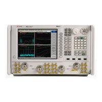
Keysight PNA-X N5249A Service Manual (556 pages)
2-Port and 4-Port PNA-X Microwave Network Analyzers 10 MHz -13.5 GHz/10 MHz -26.5 GHz/10 MHz -8.5 GHz
Brand:
Keysight
| Category:
Measuring Instruments
| Size: 28 MB
Table of Contents
Safety Notices
2
Table of Contents
3
Safety and Regulatory Information
11
Information in this Chapter
11
Chapter One At-A-Glance
11
Safety Symbols
12
General Safety Considerations
13
Safety Earth Ground
13
Before Applying Power
13
Servicing
15
Electrostatic Discharge Protection
17
Regulatory Information
19
Instrument Markings
19
Lithium Battery Disposal
20
General Product Information
21
Information in this Chapter
21
Chapter Two At-A-Glance
21
Maintenance
22
Physical Maintenance
22
Electrical Maintenance
22
Analyzer Options, Accessories, and Upgrades Available
23
Pulse I/O Adapter-N1966A
23
Required Service Test Equipment
24
Keysight Support, Services, and Assistance
26
Service and Support Options
26
Contacting Keysight
26
Shipping Your Analyzer to Keysight for Service or Repair
27
Tests and Adjustments
29
Information in this Chapter
29
Conventions Used for Hardkeys, Softkeys, and Menu Items
29
Chapter Three At-A-Glance
29
Before You Begin
32
Verify the Operating Environment
32
Protect against Electrostatic Discharge (ESD)
32
Allow the Analyzer to Warm up
33
Review the Principles of Connector Care
33
About System Verification and Performance Tests
35
System Specifications
35
Instrument Specifications
36
System Verification Procedure
36
Performance Tests
36
Certificate of Calibration
37
ANSI/NCSL Z540.3-2006 and ISO/IEC Verification
38
Non-Standards Compliant Verification
39
Preliminary Checks
40
The Operator's Check
40
The Test Port Cable Checks
43
System Verification
50
What the System Verification Verifies
50
Measurement Uncertainty
50
Measurement Traceability
51
Performing System Verification
52
Performance Tests
60
Source Power Accuracy Test
60
Source Maximum Power Output Test
61
Source Power Linearity Test
62
Frequency Accuracy Test
63
Trace Noise Test
64
Receiver Compression Test
65
Noise Floor Test
66
Calibration Coefficients Test
67
Dynamic Accuracy Test - Version 1
68
Dynamic Accuracy Test - Version 2
69
System Noise Figure Test
71
Noise Jitter Test
72
Noise Receiver Linearity Test
72
Noise Receiver Compression Test
74
Adjustments
76
10 Mhz Frequency Reference Adjustment
76
Synthesizer Bandwidth Adjustment
77
Source Adjustment
77
IF Gain Adjustment
78
Receiver Characterization
78
Receiver Adjustment
79
EE Default Adjustment
81
IF Response Adjustment (Option 090, 093, or 094 Only)
81
Noise Figure Adjustment (Available Only with Option 029 Installed)
82
Troubleshooting
85
Information in this Chapter
85
Chapter Four At-A-Glance
86
Conventions Used for Hardkeys, Softkeys, and Menu Items
86
Operating the Analyzer with Covers Removed
87
Protect against Electrostatic Discharge (ESD)
88
Assembly Replacement Sequence
89
Getting Started with Troubleshooting
90
Check the Basics
90
Troubleshooting Organization
90
Power up Troubleshooting
92
Power Supply Check
93
Troubleshooting LCD Display Problems
99
Front Panel Troubleshooting
100
Front Panel Keypad and RPG Test
100
A3 Display Test
103
Checking the A2 USB Board
103
A1 Front Panel Interface Board
104
Rear Panel Troubleshooting
105
Checking the USB Ports
105
Checking the CONTROLLER Port
105
LAN Troubleshooting
106
Measurement System Troubleshooting
113
Before You Begin-Consider: Where Do You See a Problem
113
Verifying the A, B, C, D, and R Traces (Standard S-Parameter Mode)
114
Where to Begin Troubleshooting
116
Checking the Source Group
119
Checking the Signal Separation Group
124
Checking the Receiver Group
128
Instrument Block Diagrams Sheet 1
133
Microwave PNA, N5241A/42A/49A 2-Port
133
Instrument Block Diagrams Sheet 2
135
Microwave PNA, N5241A/42A/49A 2-Port with Option H85
135
Instrument Block Diagrams Sheet 3
137
Microwave PNA, N5241A/42A/49A 4-Port
137
Instrument Block Diagrams Sheet 4
139
Microwave PNA, N5241A/42A/49A 4-Port with Option H85
139
Theory of Operation
141
Information in this Chapter
141
Chapter Five At-A-Glance
141
Network Analyzer System Operation
143
Functional Groups of the Network Analyzer
144
Synthesized Source Group Operation
148
Basic Operation
148
A4, A13, and A11 13.5 Ghz Synthesizer Boards
152
A5 and A8 26.5 Ghz Source Boards
153
A21 Multiplier/Amplifier 26.5 Board (HMA26.5)
153
A10 Frequency Reference Board
154
A19 Test Set Motherboard
154
Signal Separation Group Operation
158
Configurable Test Set
158
A25-A28 Bridges
159
A29-A32 Test Port Couplers
159
A34-A37 65-Db Source Step Attenuators and A38-A41 Bias Tees (Optional)
162
A46-A49 Mechanical Switches and A50 Combiner (Optional)
162
Receiver Group Operation
163
A42-A45 35-Db Receiver Step Attenuators (Optional)
163
A33 Reference Mixer Switch
163
A23 and A24 Mixer Bricks
163
A20 if Multiplexer Board
164
A12 SPAM Board (Analog Description)
165
Noise Measurement Group Operation (Option 029)
168
A52 Test Port 1 Option 029 Switch
168
A53 Test Port 2 Option 029 Switch
168
A54 Test Port 2 Option 029 Bridge
168
A55 Noise Downconverter
168
A7 Noise Receiver Board
169
Digital Processing and Digital Control Group Operation
171
Front Panel Subgroup
173
Data Acquisition and Processing Subgroup
174
Power Supply Group Operation
176
Replaceable Parts
177
Information in this Chapter
177
Chapter Six At-A-Glance
177
Ordering Information
178
Assembly Replacement Sequence
179
Rebuilt-Exchange Assemblies
180
Replaceable Parts Listings
182
Front Panel Assembly, Front Side, All Options
187
Front Panel Assembly, Back Side, All Options
190
Top Assemblies and Cables, All Options
194
2-Port Configuration, Option 200
201
2-Port Configuration, Options 200/219
210
2-Port Configuration, Options 200/219/029
220
2-Port Configuration, Options 200/219/H85
229
2-Port Configuration, Options 200/219/029/H85
238
2-Port Configuration, Options 200/219/224
247
2-Port Configuration, Options 200/219/224/029
257
2-Port Configuration, Options 200/219/224/H85
267
2-Port Configuration, Options 200/219/224/029/H85
276
4-Port Configuration, Option 400
286
4-Port Configuration, Options 400/419
297
4-Port Configuration, Options 400/419/029
311
4-Port Configuration, Options 400/419/H85
325
4-Port Configuration, Options 400/419/029/H85
336
4-Port Configuration, Options 400/419/423
348
4-Port Configuration, Options 400/419/423/029
362
4-Port Configuration, Options 400/419/423/H85
377
4-Port Configuration, Options 400/419/423/029/H85
390
Rear Panel Assembly, All Options
405
Top Hardware and Miscellaneous Parts, All Options
408
Bottom Hardware and Miscellaneous Parts
411
Internal Hardware and Miscellaneous Parts, All Options
416
External Hardware and Miscellaneous Parts, All Options
418
Miscellaneous Part Numbers
420
Repair and Replacement Procedures
423
Information in this Chapter
423
Chapter Seven At-A-Glance
423
Personal Safety Warnings
424
Electrostatic Discharge (ESD) Protection
425
Removal and Replacement Procedures
426
Removing the Covers
428
Removing and Replacing the Front Panel Assembly
430
Removing and Replacing the A1-A3 and Other Front Panel Subassemblies
432
Removing and Replacing the A4-A13 Boards (for Analyzers with Serial Numbers Prefixed MY/SG/US5150 and Below.)
436
Removing and Replacing the A4-A13 Boards
436
Removing and Replacing the A14 System Motherboard
442
Removing and Replacing the A15 Midplane Board
445
Removing and Replacing the A16 Power Supply Assembly
447
Removing and Replacing the A17 CPU Board Assembly
449
Removing and Replacing the A18 GPIB Board
451
Removing and Replacing the A19 Test Set Motherboard
453
Removing and Replacing the A20 if Multiplexer Board
456
Removing and Replacing the A21 HMA26.5
458
Removing and Replacing the A22 Splitter
460
Removing and Replacing the A23 and A24 Mixer Bricks
462
Removing and Replacing the A25-A28 Bridges and Bridge Mounting Brackets
464
Removing and Replacing the A29-A32 Test Port Couplers
466
Removing and Replacing the A33 Reference Mixer Switch
469
Removing and Replacing the A34-A37 Source Attenuators, the A38-A41 Bias Tees, and the A42-A45 Receiver Attenuators
471
Removing and Replacing the A38-A41 Bias Tees
474
Removing and Replacing the A46-A49 Bypass Switches and the A50 Combiner
477
Removing and Replacing the A51 Hard Disk Drive (HDDA) or Solid State Drive (SSD)
479
Removing and Replacing the A52 and A53 Option 029 Test Port Switches
483
Downconverter
486
Removing and Replacing the Rear Panel
488
Removing and Replacing the Front Panel LED Boards
490
Removing and Replacing the Fans
492
Removing and Replacing the Lithium Battery
494
Post-Repair Procedures
498
General Purpose Maintenance Procedures
503
Information in this Chapter
503
Chapter Eight At-A-Glance
503
Conventions Used for Hardkeys, Softkeys, and Menu Items
503
Error Terms
504
Using Error Terms as a Diagnostic Tool
504
Performing Measurement Calibration
505
Using Flowgraphs to Identify Error Terms
506
Accessing Error Terms
509
Error Term Data
511
Option Enable Utility
514
Accessing the Option Enable Utility
514
Option Entitlement Certificate
514
Enabling or Removing Options
515
Repairing and Recovering Option Data
516
Installing or Changing a Serial Number
517
Firmware Upgrades
518
How to Check the Current Firmware Version
518
Downloading from the Internet
518
Operating System Recovery
519
Recovering from Hard Disk Drive Problems
519
Correction Constants
520
Storing Correction Constants
520
Advertisement
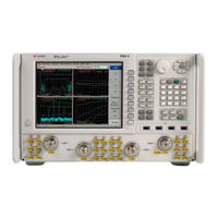
Keysight PNA-X N5249A Configuration Manual (37 pages)
PNA Family Microwave Network Analyzers
Brand:
Keysight
| Category:
Measuring Instruments
| Size: 3 MB
Table of Contents
Table of Contents
2
PNA Family Network Analyzer Configurations
5
Test Set and Power Configuration Options
5
Application Options
6
Accessories, Calibration Options
7
PNA-X Series Test Set and Power Configuration Options
8
PNA Series Test Set and Power Configuration Options
10
PNA-L Series Test Set and Power Configuration Options
12
PNA Family Application Options
13
Measurement Applications
13
Noise Figure Options
15
PNA-X Block Diagrams with Noise Figure Option
17
Noise Figure Options Summary
18
Pulse, Antenna, MM-Wave
19
Accessories
20
PNA Family Network Analyzer Upgrade Kits
21
Frequency, Test Ports, Test Set and Power Configurations
21
Application Options
22
Upgrade Paths
24
Applications
25
Material Measurements
25
Signal Integrity Measurements
25
Multiport Measurements
25
Millimeter-Wave Measurements
25
Cables and Adapter Sets
27
Calibration Kits
27
For Devices with 1.0 MM Connectors
28
For Devices with 1.85 MM Connectors
28
For Devices with 2.4 MM Connectors
29
For Devices with K (2.92 MM) Connectors
29
For Devices with 3.5 MM, SMA, or 2.92 MM Connectors
30
For Devices with 3.5 MM or SMA Connectors
31
For Devices with Type-N Connectors
33
For Devices with 7 MM Connectors
34
For Devices with Waveguide
34
Verification Kits
35
Measurement Accessories
27
General Accessories
35
Spare Drive
35
Probe
36
Power Meters and Sensors
36
Comb Generators
36
Amplifiers
36
Couplers
36
Equipment Rack Accessories
36
Monitors
36
Interface Cables
36
Keysight PNA-X N5249A Security Features And Document Of Volatility (34 pages)
PNA Network Analyzers
Brand:
Keysight
| Category:
Measuring Instruments
| Size: 0 MB
Table of Contents
Table of Contents
4
1 Contacting Keysight Sales and Service Offices
5
2 Products Covered by this Document
6
Determining Installed Options and Processor Assembly Type
7
3 Security Terms and Definitions
8
4 Non-Volatile and Volatile Memory
9
Summary of Non-Volatile Instrument Memory
10
Disk Drive Partitioning
15
CPU Types and Mass Storage
16
Summary of Volatile Memory
17
LAN/USB/GPIB Devices
19
How to Disable USB, GPIB, and LAN
19
5 Memory Sanitization and Removal Procedures
20
Instrument Sanitization Procedure
22
Application License Key Storage
22
Replacement of Disk Drive
22
Items Required
22
Procedure
23
6 Disk Drive Removal Procedure
25
7 User and Remote Interface Security Measures
28
SCPI/GPIB Control of Interfaces
28
Operating System Security Features
28
USB Interfaces
29
Disabling or Enabling Autorun/Autoplay
29
Configuring USB for Read-Only
29
8 Procedure for Declassifying a Faulty Instrument
31
Appendix A References
32
Advertisement
Keysight PNA-X N5249A Installation Note (50 pages)
Noise Figure Measurement Capability Upgrade Kit
Brand:
Keysight
| Category:
Measuring Instruments
| Size: 3 MB
Table of Contents
Safety Notices
2
Getting Assistance from Keysight
4
Initial Inspection
4
Getting Prepared
5
Keysight PNA-X N5249A Upgrade Kit (50 pages)
Noise Figure Measurement Capability Upgrade Kit
Brand:
Keysight
| Category:
Measuring Instruments
| Size: 3 MB
Keysight PNA-X N5249A Manual (16 pages)
Noise Figure Board (No Tabs) Revision Kit
Brand:
Keysight
| Category:
Test Equipment
| Size: 1 MB
Table of Contents
Safety Notices
2
Description of the Upgrade
3
Getting Assistance from Keysight
4
Contacting Keysight
4
Getting Prepared
5
Items Included in the Upgrade Kit
7
Overview of the Installation Procedure
7
Advertisement
Related Products
keysight N5249B
Keysight N5249AU- 927
Keysight PNA-X N5249A-H85
Keysight N5249BU-229
Keysight PNA-X N5242A
keysight PNA-X N5241B
Keysight N5244AU- H29
Keysight N5242-60120
Keysight N5245AU-940
keysight PNA-X Series
Keysight Categories
Measuring Instruments
Test Equipment
Multimeter
Portable Generator
Power Supply
More Keysight Manuals
Login
Sign In
OR
Sign in with Facebook
Sign in with Google
Upload manual
Upload from disk
Upload from URL