Sign In
Upload
Manuals
Brands
KAESER KOMPRESSOREN Manuals
Air Compressor
MOBILAIR M55 PE
KAESER KOMPRESSOREN MOBILAIR M55 PE Manuals
Manuals and User Guides for KAESER KOMPRESSOREN MOBILAIR M55 PE. We have
1
KAESER KOMPRESSOREN MOBILAIR M55 PE manual available for free PDF download: Operator's Manual
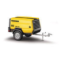
KAESER KOMPRESSOREN MOBILAIR M55 PE Operator's Manual (376 pages)
Portable Rotary Screw Compressor
Brand:
KAESER KOMPRESSOREN
| Category:
Air Compressor
| Size: 34.82 MB
Table of Contents
Table of Contents
3
Regarding this Document Using this Document
13
Further Documents
13
Copyright
13
Symbols and Labels
13
Warnings
13
Potential Damage Warnings
14
Tab. 1 Danger Levels and Their Definition (Personal Injury)
14
Tab. 2 Danger Levels and Their Definition (Damage to Property)
14
Other Alert Notes and Their Symbols
15
Technical Data Nameplate
16
Vehicle Identification Number
16
Options Overview
16
Tab. 3 Nameplate
16
Air Treatment
17
Air Distributor
17
Low Temperature Equipment
17
Fig. 1 Option Label MOBILAIR M55PE with Options
17
Tab. 4 Air Treatment Options
17
Tab. 5 Air Distributor Option
17
Exhaust Gas After-Treatment
18
GSM/GPS Modem
18
Lighting
18
Frame Design for Stationary Machines
18
Tab. 6 Low Temperature Equipment Options
18
Tab. 7 Exhaust Gas After-Treatment Options
18
Tab. 8 GSM/GPS Modem
18
Tab. 9 Lighting Options
18
Machine (Without Options)
19
Sound Pressure Level [Db(A)]
19
Tightening Torque
19
Tab. 10 Options for Stationary Frame Design
19
Tab. 11 Guaranteed Sound Pressure Level [Db(A)]
19
Tab. 12 Torques for M4-M8 Screws
19
Tab. 13 Torques for M10-M24 Screws
19
Ambient Conditions
20
Additional Specifications
20
Chassis
20
Chassis Options
20
Machines with Stationary Frame Design
20
Weight of Machines with Stationary Frame Design
20
Tab. 14 Torques for Lifting Eye Screws
20
Tab. 15 Ambient Conditions
20
Compressor
21
Variable Pressure Flow Rate Control (Pv Control)
21
Tab. 16 Weight of the Machine
21
Tab. 17 Maximum Working Pressure
21
Fig. 2 Nominal System Pressure / Flow Rate Diagram
22
Tab. 18 Flow Rate Depending on the Nominal System Pressure
22
Fig. 3 Nominal System Pressure / Engine Speed Diagram
23
Tab. 19 Flow Rate Depending on the Nominal System Pressure
23
Tab. 20 Nominal System Pressure and Engine Speed
23
Compressed Air Outlet
24
Safety Relief Valves
24
Temperature
24
Cooling Oil Recommendation
24
Tab. 21 Nominal System Pressure and Engine Speed
24
Tab. 22 Compressed Air Distributor
24
Tab. 23 Safety Relief Valve Activating Pressure
24
Tab. 24 Required Temperatures Readiness to Switch to LOAD Mode
24
Tab. 25 Airend Discharge Temperature
24
Tab. 26 Cooling Oil Recommendation
25
Cooling Oil Charge
26
Engine
26
Engine Specification
26
Oil Recommendations
26
Tab. 27 Cooling Oil Recommendation (Food Processing)
26
Tab. 28 Cooling Oil Charge
26
Tab. 29 Engine Specification
26
Fuel Recommendation
27
Tab. 30 Engine Oil Recommendation
27
Tab. 31 Viscosity Class for First Fill
27
Engine Coolant Recommendation
28
Tab. 32 Water Quality Specification
28
Fluid Volumes
29
Batteries
29
Tab. 33 Initial Fill of Coolant Cooler
29
Tab. 34 Fluid Volumes
29
Tab. 35 Batteries
29
Options
30
Air Treatment Options
30
Low Temperature Equipment
30
Tab. 36 Interrelation between Compressed Air Treatment and Compressed Air Quality
30
Tab. 37 Ambient Conditions, Low Temperature Equipment
30
Tab. 38 Insulated Pressure Hoses
30
Safety and Responsibility Basic Instructions
31
Specified Use
31
Incorrect Use
31
User's Responsibilities
31
Observe Statutory and Universally Accepted Regulations
31
Determining Personnel
32
Complying with Inspection Schedules and Accident Prevention Regulations
33
Dangers
33
Safely Dealing with Sources of Danger
33
Tab. 39 Inspection Intervals According to Ordinance on Industrial Health and Safety
33
Safe Machine Operation
36
Organizational Measures
40
Danger Areas
40
Safety Devices
40
Safety Signs
40
Tab. 40 Danger Areas
40
Fig. 4 Location of Safety Signs (Outside)
41
Tab. 41 Safety Signs
42
Fig. 5 Location of Safety Signs (Inside)
43
Noise Control Requirements
44
Tab. 42 Safety Signs
44
Emergencies
45
Correct Actions in the Event of a Fire
45
Treating Injuries from Handling Operating Fluids/Materials
45
Warranty
46
Noise Emissions Warranty
46
Identifying the Effects of Improper Modifications
46
Environmental Protection
47
Design and Function Bodywork
48
Fig. 6 Bodywork
48
Machine Structure
50
Fig. 7 Right-Hand Door Opened
50
Machine Function
51
Fig. 8 Machine Overview
52
Operating Modes and Control Mode
53
Machine Operating Modes
53
MODULATING Control
54
Safety Devices
54
Monitoring Functions with Shut-Down
54
Further Safety Devices
54
SIGMA CONTROL SMART Control Panel
55
Fig. 9 SIGMA CONTROL SMART Control Panel - Overview
55
Variable Pressure Flow Rate Control (Pv Control)
56
Exhaust Gas After-Treatment
56
Engine Optimization
56
Tab. 43 Instrument Panel Keys and Displays
56
Exhaust Gas Treatment System
57
Regeneration of the Diesel Particulate Filter
58
Fig. 10 Principle of Treatment Devices
58
Options
59
Air Treatment Options
59
Fig. 11 Compressed Air Options
60
GSM/GPS Modem
61
Document Bag
61
Fig. 12 Location of the GSM/GPS Modem Inside the Machine
61
Tab. 44 Compressed Air Quality With/Without Heat Exchanger
61
Transport Options
62
Frame Design Options for Stationary Machines
62
Fig. 13 Document Bag Option
62
Tab. 45 Stationary Machines
63
Installation and Operating Conditions
64
Ensuring Safety
64
Installation Conditions
64
Fig. 14 Minimum Distance from Excavations/Slopes and Walls
65
Requirements for Positioning on a Lorry Platform
66
Installation
67
Ensuring Safety
67
Reporting Transport Damage
67
Perform Regular Maintenance on the Chassis
67
Securing the Parked Machine
67
Fitting the Machine Feet
68
Fig. 15 Mounting Machine Foot/Rubber Pad
68
Initial Start-Up Ensuring Safety
69
Before Initial Start-Up (or Recommissioning)
69
Instructions to be Observed before Commissioning or Recommissioning
69
Special Measures for Recommissioning after Storage
70
Checking Installation and Operating Conditions
70
Tab. 46 Special Measures for Recommissioning after Storage
70
Low-Temperature Operation
71
Checking the Warm-Up Function in Low-Temperature Conditions
71
Tab. 47 Checking Installation and Operating Conditions
71
Starting Assistance
72
Fig. 16 Jumper Cable Connection Diagram
73
Operation
75
Ensuring Safety
75
Starting up and Shutting down
76
Control Panel
76
Fig. 17 Control Panel with Starting Instruments
76
SIGMA CONTROL SMART Control Unit
77
Controller ON/OFF Switch
77
Fig. 18 Keys and Indicators, SIGMA CONTROL SMART Control Unit
77
Observing the Quick Reference Guide
78
Fig. 19 Location, "Controller ON/OFF" Switch
78
Fig. 20 Quick Reference Guide for Start-Up Procedure
78
Operating the Machine in Winter Conditions
79
Fig. 21 Quick Reference Guide for Shutdown Procedure
79
Starting the Machine
80
Setting the Compressed Air Discharge Pressure
80
Fig. 22 Quick Access Adjustment Compressed Air Output Pressure
81
Shutting down the Machine
82
Fig. 23 Setting the Compressed Air Discharge Pressure
82
Shutting down in an Emergency
83
Refueling the Machine
84
Using the Correct Type of Fuel
84
Tab. 48 Measures Required Should the Fuel Tank be Filled with the Incorrect Fuel Type
85
Filling the Fuel Tank at a Pump by Means of a Refuelling Nozzle
86
Fig. 24 Filling the Tank with the Correct Fuel Type
86
Tab. 49 Fuel / Fuel Specification
86
Filling the Fuel Tank on a Construction Site by Means of a Canister
87
Confirming Alarm and Warning Messages
88
Confirming Alarm Messages
88
Confirming Warning Messages
88
Cleaning the Machine after Operation
89
Cleaning the Exterior of the Machine
90
Clean the Interior of the Machine
90
Operating the Options
91
Bypassing/Switching on the Heat Exchanger
91
Fig. 25 Bypassing/Switching on the Heat Exchanger
92
Tab. 50 Directional Control Valve Position and Selected Compressed Air Quality
92
Tab. 51 Directional Control Valve Position and Selected Compressed Air Quality
93
Fault Recognition and Rectification
94
Basic Instructions
94
Analysing SIGMA CONTROL SMART Messages
94
Fault Messages on the Controller (Machine Off)
94
Tab. 52 Alarm Messages and Actions Relating to "Engine Fault
96
Tab. 53 Fault Messages and Actions Relating to "Compressor Fault
96
Warning Messages on the Controller
97
Tab. 54 Fault Messages and Actions Relating to "Controller Fault
97
Tab. 55 Fault Messages and Actions Relating to "General Faults
97
Tab. 56 Warning Messages and Measures Relating to the Engine
98
Evaluating Engine Faults and Alarms
99
Engine Refuses to Start or Does Not Turn over
99
Tab. 57 Warning Messages and Measures Relating to the Compressor
99
Tab. 58 General Warning Messages and Measures
99
Engine Does Not Reach Full Speed
100
Tab. 59 Fault: Engine Refuses to Start or Comes to a Stop
100
Tab. 60 Alarm: "Engine Does Not Reach Full Speed
100
Analyzing Compressor Faults and Alarms
101
Working Pressure too High
101
Working Pressure too Low
101
Tab. 61 Fault: Working Pressure too High
101
Tab. 62 Fault: Working Pressure too Low
101
Safety Relief Valve Blows off
102
Machine Overheating
102
Tab. 63 Fault: Safety Relief Valve Blowing off
102
Tab. 64 Fault: Machine Overheating
102
Too Much Oil Residue in the Compressed Air
103
Oil Flows from the Compressor Air Filter after Shutdown
103
High Moisture Content in the Compressed Air
103
Tab. 65 Alarm: "Too Much Oil Residue in the Compressed Air
103
Tab. 66 Alarm: "Oil Flows from the Compressor Air Filter after Shutdown
103
Tab. 67 Fault: High Moisture Content in the Compressed Air
103
10 Maintenance
104
Ensuring Safety
104
Tab. 68 Advise Others that the Machine Is Being Serviced
104
Observing Maintenance Messages in the Controller
105
Evaluating Maintenance Messages
105
Tab. 69 Maintenance Messages and Required Measures
105
Completing Maintenance
106
Following the Maintenance Plans
107
Logging Maintenance Work
107
Maintenance Tasks after Commissioning
107
Regular Maintenance Tasks
107
Tab. 70 Maintenance Tasks on the Machine after Commissioning
107
Tab. 71 Maintenance Intervals and Regular Maintenance Tasks
108
Fig. 59 Maintenance Indicator
110
Tab. 72 Regular Machine Maintenance Tasks
111
Tab. 73 Regular Maintenance Tasks for Options
111
Drive Engine Maintenance
112
Coolant Cooler Maintenance
112
Fig. 26 Checking the Coolant Level
113
Fig. 27 Recommended Mixture Ratio for Coolant
114
Tab. 74 Coolant Mixture Table
115
Fig. 28 Draining the Coolant
116
Engine Air Filter Maintenance
117
Tab. 75 Specific Message Code for "Service Engine Air Filter
117
Fig. 29 Maintenance Indicator
118
Fig. 30 Cleaning the Dust Evacuator Valve
118
Fig. 31 Engine Air Filter Maintenance
119
Fig. 32 Removing both Filter Elements
120
Fuel System Maintenance
121
Fig. 33 Cleaning the Primary Filter Element
121
Fig. 34 Servicing the Fuel System
122
Fig. 35 Bleeding the Fuel System
123
Fig. 36 Warning Message: Water Level, Fuel Prefilter
124
Fig. 37 Empty the Fuel Prefilter and Water Separator
124
Fig. 38 Changing the Fuel Prefilter Cartridge
125
Fig. 39 Fuel Filter Maintenance
126
Checking the Engine Oil Level
127
Fig. 40 Checking the Engine Oil Level
127
Engine Oil Filling and Topping off
128
Changing the Engine Oil
129
Tab. 76 Specific Message Code for "Change the Engine Oil
129
Replacing the Engine Oil Filter
130
Fig. 41 Draining the Engine Oil
130
Tab. 77 Specific Message Code for "Change the Oil Filter
131
Fig. 42 Changing the Oil Filter
132
Replacing the Engine Oil Separator Catridge
133
Fig. 43 Replacing the Oil Separator Element
133
Drive Belt Maintenance
134
Fig. 44 Belt Guard Attachment
134
Fig. 45 Check the Drive Belt Seating
135
Fig. 46 Manually Checking the Belt Tension
136
Fig. 47 Changing/Tensioning the Drive Belt
137
Having the Anti-Vibration Mount Checked
138
Battery Maintenance
138
Fig. 48 Example for Anti-Vibration Mount of Drive Engine
138
Fig. 49 Safety Signs - Warning Labels on the Battery
139
Tab. 78 Starter Batteries Charge Level
140
Servicing Components in the Exhaust Gas After-Treatment System
142
Fig. 50 Heat Shield, Exhaust Gas After-Treatment
143
Fig. 51 Exhaust Gas After-Treatment with Diesel Particulate Filter
144
Compressor Maintenance
145
Checking the Cooling Oil Level
145
Fig. 52 Checking the Cooling Oil Level
145
Filling or Topping off the Cooling Oil
146
Changing the Cooling Oil
147
Tab. 79 Specific Message Code for "Change the Cooling Oil
147
Fig. 53 Draining the Compressor Cooling Oil
149
Fig. 54 Airend Screw Plug
150
Tab. 80 Specific Cooling Oil Volumes
151
Replacing the Compressor Oil Filter
152
Tab. 81 Specific Message Code for "Change the Oil Filter
152
Fig. 55 Changing the Oil Filter
153
Oil Separator Tank Dirt Trap Maintenance
154
Fig. 56 Oil Separator Tank Dirt Trap Maintenance
155
Tab. 82 Dirt Trap Screw Plug Torque
155
Fig. 57 Install the Male Stud Fitting
156
Changing the Oil Separator Cartridge
157
Fig. 58 Changing the Oil Separator Cartridge
157
Compressor Air Filter Maintenance
159
Tab. 83 Specific Message Code for "Service Air Filter
159
Fig. 60 Cleaning the Dust Evacuator Valve
160
Fig. 61 Compressor Air Filter Maintenance
161
Fig. 62 Removing both Filter Elements
162
Cleaning the Cooler
163
Fig. 63 Cleaning the Filter Element
163
Cleaning the Oil Cooler and Coolant Cooler
164
Fig. 64 Cleaning the Cooler
165
Checking the Screw Connections
166
General Guideline Values for Tightening Torques
166
Specific Guideline Values for Tightening Torques
167
Sealed Screw Connections
167
Check Wing Doors
167
Maintain Rubber Sealing Strips
168
Checking Function of Closed Enclosure
168
Checking Connecting Elements of Enclosure
168
Check/Replace Hose Lines
169
Replace the Fuel Lines of the Drive Engine
169
Fig. 65 Connecting Rod Alignment
169
Replace the Pressure Hoses of the Engine
170
Replace the Pressure Hoses of the Compressor
170
Check Safety Functions
170
Check the EMERGENCY STOP Push Button
170
Have the Actuating Pressure of the Safety Relief Valve Checked
171
Having Excessive Temperature Shut-Down Function Checked
171
Tab. 84 Safety Relief Valve Actuating Pressure
171
Maintenance for Optional Items
172
Compressed Air Aftercooler Maintenance
172
Tab. 85 Safety Shut-Down at Excessive Airend Discharge Temperature
172
Fig. 66 Cleaning the Compressed Air After-Cooler
173
Maintenance of the Water Separator Dirt Trap
174
Fig. 67 Clean the Dirt Trap
175
Filter Combination Maintenance
176
Fig. 68 Combination Filter Maintenance
177
Tab. 86 Replacing the Filter Elements
179
Documenting Maintenance and Service Work
181
Tab. 87 Maintenance Log
181
11 Spares, Operating Materials, Service
182
Note the Nameplate
182
Ordering Maintenance Parts and Operating Fluids/Materials
182
Tab. 88 Compressor Maintenance Parts
182
Kaeser Air Service
183
Replacement Parts for Service and Repair
183
Spare Parts Overview
183
Tab. 89 Engine Maintenance Parts
183
12 Decommissioning, Storage and Transport
239
Decommissioning
239
Temporary Decommissioning
239
Tab. 90 "Temporarily Decommissioned" Information Notice
239
Long-Term De-Commissioning/Storage
240
Tab. 91 "Long-Term Decommissioning/Storage" Checklist
240
Transportation
241
Safety
241
Tab. 92 Notice Text: "Long-Term Decommissioned/Storage
241
Transporting the Machine by Crane
242
Fig. 69 Lifting Eye for Transportation by Crane
242
Transporting by Forklift Truck
243
Fig. 70 Prohibition Signs for Forklift Transport
244
Fig. 71 Forklift Example: Lifting Accessory Components
244
Fig. 72 Ensure both Fork Prongs Are Positioned under the Machine
245
Fig. 73 Lifting the Machine with a Forklift
246
Transporting as a Load
247
Fig. 74 Example: Transporting a Machine by Forklift
247
Fig. 75 Example: Improper Load Securing
248
Fig. 76 Example: Proper Load Securing Via Lashing Points Provided
249
Fig. 77 Bracing as Load Securing (Machine in Stationary Configuration)
250
Storage
251
Disposal
251
Removing the Batteries
251
Draining Operating Fluids
252
Fig. 78 Battery Labelling
252
Tab. 93 Machine Fluids
252
Draining Condensate
253
Removing Filters/Filter Elements
253
Tab. 94 Machine Option Fluids
253
Tab. 95 Machine Filters/Filter Elements
253
Tab. 96 Machine Option Filters/Filter Elements
253
Disposing of the Machine
254
13 Annex
255
Identification
255
Identification of the Machine
255
Identification of the Drive Engine
255
Fig. 79 Identification of the Machine
255
Fig. 80 Identification of the Drive Engine
255
Identification of the Exhaust Gas After-Treatment System
256
Pipeline and Instrument Flow Diagram (P+I Diagram)
256
Fig. 81 Identification of the Exhaust Gas After-Treatment System
256
Dimensional Drawings
261
Dimensional Drawing - Chassis
261
Dimensional Drawing, Stationary Version
263
Dimensional Drawing, Stationary Version
265
Wiring Diagrams
267
Electrical Diagram
267
Lighting and Signaling System Connection
295
Fuel Circulation Diagram
299
Operating Instructions for Compressed Air Filter (Combination Filter)
302
Advertisement
Advertisement
Related Products
KAESER KOMPRESSOREN M170
KAESER KOMPRESSOREN MOBILAIR M58utility
KAESER KOMPRESSOREN SIGMA CONTROL SMART M114
KAESER KOMPRESSOREN MOBILAIR M27
KAESER KOMPRESSOREN SIGMA CONTROL SMART MOBILAIR M82
KAESER KOMPRESSOREN M250
KAESER KOMPRESSOREN M43
KAESER KOMPRESSOREN CSD 102
KAESER KOMPRESSOREN CSD 122
KAESER KOMPRESSOREN CSD 82
KAESER KOMPRESSOREN Categories
Air Compressor
Controller
Blower
Dryer
Water Filtration Systems
More KAESER KOMPRESSOREN Manuals
Login
Sign In
OR
Sign in with Facebook
Sign in with Google
Upload manual
Upload from disk
Upload from URL