Sign In
Upload
Manuals
Brands
KAESER KOMPRESSOREN Manuals
Air Compressor
MOBILAIR M27
KAESER KOMPRESSOREN MOBILAIR M27 Manuals
Manuals and User Guides for KAESER KOMPRESSOREN MOBILAIR M27. We have
1
KAESER KOMPRESSOREN MOBILAIR M27 manual available for free PDF download: Operator's Manual
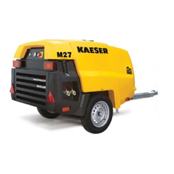
KAESER KOMPRESSOREN MOBILAIR M27 Operator's Manual (304 pages)
Screw Compressor
Brand:
KAESER KOMPRESSOREN
| Category:
Air Compressor
| Size: 19.56 MB
Table of Contents
Table of Contents
3
Regarding this Document Using this Document
13
Further Documents
13
Copyright
13
Symbols and Labels
13
Warnings
13
Tab. 1 Danger Levels and Their Definition (Personal Injury)
13
Potential Damage Warnings
14
Other Alert Notes and Their Symbols
14
Tab. 2 Danger Levels and Their Definition (Damage to Property)
14
Technical Data Nameplate
16
Options
16
Tab. 3 Nameplate
16
Air Treatment
17
Tool Lubricator
17
Compressed Air Distributor
17
Tab. 4 Options Label
17
Tab. 5 Air Treatment Options
17
Tab. 6 Tool Lubricator Option
17
Non-Return Function
18
Low Temperature Equipment
18
Equipment for Fire Hazard Areas
18
Fuel De-Watering Filter
18
Battery Isolating Switch
18
Tab. 7 Compressed Air Distributor Option
18
Tab. 8 Non-Return Option
18
Tab. 9 Low Temperature Equipment Options
18
Tab. 10 Optional Equipment for Fire Hazard Areas
18
Tab. 11 Option Ne: Fuel De-Watering Filter
18
Generator
19
Chassis
19
Lighting
19
Tab. 13 Generator Option
19
Tab. 14 Chassis Options
19
Frame Design for Stationary Machines
20
Sealed Floor Pan
20
Hose Reels
20
Anti-Theft Device
20
Tab. 15 Lighting Options
20
Tab. 16 Options for Stationary Frame Design
20
Tab. 17 Sealed Floor Pan Option
20
Tab. 18 Hose Reel Option
20
Tab. 19 Anti-Theft Device Option
20
Machine (Without Options)
21
Sound Pressure Level
21
Tightening Torques for Screws
21
Ambient Conditions
21
Tab. 20 Sound Pressure Level
21
Tab. 21 Tightening Torques for Screws (Property Class 8.8, Coefficient of Friction Μ = 0.12)
21
Tab. 22 Torque Cover Fixing Screws Oil Separator Tank
21
Tab. 23 Torques for Lifting Eye Screws
21
Tab. 24 Ambient Conditions
21
Additional Specifications
22
Chassis
22
Chassis Options
22
Machines with Stationary Frame Design
22
Weight of Machines with Stationary Frame Design
22
Compressor
22
Working Pressure and FAD
22
Tab. 25 Weight of the Machine
22
Tab. 26 Working Gauge Pressure and FAD
22
Compressed Air Outlet
23
Air Quality at the Compressed Air Outlets
23
Tab. 27 Compressed Air Distributor
23
Tab. 28 Interrelation between Compressed Air Treatment and Compressed Air Quality
23
Safety Relief Valve
24
Select Temperature
24
Cooling Oil Recommendation
24
Tab. 29 Relief Valve Activating Pressure
24
Tab. 30 Machine Temperatures
24
Tab. 31 Airend Package Discharge Temperature
24
Tab. 32 Cooling Oil Recommendation
25
Tab. 33 Cooling Oil Recommendation (Food Processing)
25
Cooling Oil Charge
26
Engine
26
Engine Data
26
Oil Recommendation
26
Tab. 34 Cooling Oil Charge
26
Tab. 35 Engine Data
26
Fuel Recommendation
27
Engine Coolant Recommendation
27
Tab. 36 Engine Oil Recommendation
27
Tab. 37 Water Quality Parameters for Cooling Water
27
Fluid Volumes
28
Batteries
28
Tab. 38 Initial Filling of Engine Water Cooler
28
Tab. 39 Fluid Volumes
28
Options
29
Tool Lubricator
29
Low Temperature Equipment
29
Tab. 40 Batteries
29
Tab. 41 Road Breaker Lubricant Recommendation
29
Tab. 42 Ambient Conditions, Low Temperature Equipment
29
Tab. 43 Coolant Pre-Heater
29
Tab. 44 Recommended Anti-Freeze
29
Generator
30
Tab. 45 Generator Data, 400V
30
Tab. 46 Compressed Air Delivery in Generator Mode
31
Tab. 47 Connection Sockets
31
Tab. 48 Circuit Breaker
31
Tab. 49 Maximum 3-Phase Power Supply
31
Tab. 50 Maximum Single Phase Power Supply
32
Tab. 51 Generator Data 115V
32
Tab. 52 Compressed Air Delivery in Generator Mode
32
Tab. 53 Connection Sockets
33
Tab. 54 Circuit Breaker
33
Tab. 55 Maximum Single-Phase Power Supply Loading
33
Air Hose with Hose Reel
34
Tab. 56 Generator Operating Limits
34
Tab. 57 Output Power Reduction
34
Tab. 58 Additional Discharge Valve for the Air Hose
34
Safety and Responsibility Basic Instructions
35
Specified Use
35
Incorrect Use
35
User's Responsibilities
35
Observe Statutory and Universally Accepted Regulations
35
Determining Personnel
36
Adherence to Inspection Schedules and Accident Prevention Regulations
36
Dangers
36
Safely Dealing with Sources of Danger
37
Safe Machine Operation
39
Organizational Measures
43
Danger Areas
43
Safety Devices
43
Safety Signs
43
Tab. 59 Danger Areas
43
Fig. 1 Location of Safety Signs
44
Tab. 60 Safety Signs
46
Generator Operation
47
Comply with the Protective Measures against Dangerous Electric Current
47
Instructions for Safe Generator Operation
47
Connecting Extension Cables
47
Do Not Exceed the Maximum Supply System Load
48
Perform Regular Generator Inspections
48
Emergency Situations
48
Correct Fire Fighting
48
Injury from Handling Operating Fluids/Materials
49
Warranty
49
Environmental Protection
50
Design and Function Bodywork
51
Fig. 2 Bodywork
51
Component Identification
52
Fig. 3 Side View (Canopy Removed)
52
Machine Function
53
Fig. 4 Machine Overview
53
Operating Modes and Control Mode
54
Machine Operating Modes
54
MODULATING Control
54
Safety Devices
55
Monitoring Functions with Shutdown
55
Further Safety Devices
55
Options
55
Air Treatment Options
55
Fig. 5 Compressed Air Options
56
Generator Option
57
Fig. 6 Tool Lubricator
57
Tab. 61 Generator Mode Selector Switch
58
Tab. 62 Generator Operating Modes
58
Low Temperature Equipment Options
59
Fig. 7 Instrument Panel, Generator Control Box 400 V/3~/N/PE, 50 Hz
59
Fig. 8 Instrument Panel, Generator Control Box 115 V/1~/N/PE, 50 Hz, 32 a
59
Fig. 9 Coolant Pre-Heating
60
Options for Operating in Fire Hazard Areas
61
Fig. 10 Frost Protector
61
Fuel De-Watering Filter Option
62
Sealed Floor Pan Option
62
Battery Isolating Switch Option
62
Hose Reel Option
63
Anti-Theft Device Option
63
Fig. 11 Battery Isolating Switch
63
Fig. 12 Container for Safety Chain
63
Frame Design Options for Stationary Machines
64
Chassis Types of Stationary Machines
64
Tab. 63 Stationary Machines
64
Installation and Operating Conditions
65
Ensuring Safety
65
Installation Conditions
65
Fig. 13 Minimum Distance from Excavations, Slopes, or Walls
66
Requirements for Positioning on a Lorry Platform
67
Installation
68
Ensuring Safety
68
Reporting Transport Damage
68
Installing the Options
68
Fastening a Stationary Machine
68
Fig. 14 Fitting the Mounting Pads
69
Initial Start-Up Ensuring Safety
70
Before Initial Start-Up (or Recommissioning)
70
Instructions to be Observed before Commissioning or Recommissioning
70
Special Measures for Recommissioning after Storage
71
Checking Installation and Operating Conditions
71
Tab. 64 Special Measures for Recommissioning after Storage
71
Low-Temperature Operation (Winter)
72
Starting Assistance
72
Tab. 65 Checking Installation and Operating Conditions
72
Fig. 15 Jumper Cable Connection Diagram
73
Starting up Low-Temperature Equipment
74
Activating the Generator
75
Fig. 16 Coolant Pre-Heating
75
Tab. 66 Low-Temperature Equipment Checklist
75
Generator Control Box 400V with Insulation Monitoring
76
Generator Control Box 115V with Insulation Monitoring
76
Testing the Insulation Monitor
76
Fig. 17 Insulation Monitoring - 400V, 3-Phase Generator
76
Fig. 18 Insulation Monitoring - 115V, Single-Phase Generator
76
Tab. 67 Test Instructions for a Generator with a Ground Leak Detection Device
77
Operation
78
Ensuring Safety
78
Starting and Stopping
79
Commissioning the Machine
79
Fig. 19 Starting Instruments
79
Starting the Machine
80
Allow the Machine to Run up to Operating Temperature
80
Running the Machine under Load
80
Fig. 20 Warm-Up Period When Ambient Temperatures Are below 14 °F
80
Shutting down the Machine
81
Ending the Reverse Engine Run
81
Cleaning the Machine after Operation
81
Operating the Options
82
Operating the Battery Isolating Switch
82
Operating the Tool Lubricator
83
Fig. 21 Battery Isolating Switch
83
Using the Low-Temperature Equipment
84
Fig. 22 Adjusting the Tool Lubricator
84
Fig. 23 Frost Protector on and off
85
Generator Operation
86
Fig. 24 Generator Cut-In Pictogram
87
Using the Hose Reel
88
Fig. 25 Hose Reel
88
Fault Recognition and Rectification
90
Basic Instructions
90
Evaluating Engine Faults and Alarms
90
Engine Refuses to Start or Does Not Turn over
90
Engine Does Not Reach Full Speed
91
Indicator Lamp Remains on
91
Tab. 68 Fault: Engine Refuses to Start or Comes to a Stop
91
Tab. 69 Alarm: "Engine Does Not Reach Full Speed
91
Tab. 70 Alarm: "Control Lamp Remains on
91
Engine Running Backwards
92
Compressor Faults and Alarms
92
Working Pressure too High
92
Working Pressure too Low
92
Tab. 71 Fault "Motor Running Backwards
92
Tab. 72 Alarm: Working Pressure too High
92
Safety Relief Valve Blowing off
93
Machine Overheating
93
Tab. 73 Alarm: Working Pressure too Low
93
Tab. 74 Alarm: Safety Relief Valve Blowing off
93
Too Much Oil Residue in the Compressed Air
94
Oil Flows from the Compressor Air Filter after Shutdown
94
Tab. 75 Alarm: Machine Overheating
94
Tab. 76 Fault: too Much Oil Residue in the Compressed Air
94
Tab. 77 Fault: Oil Flows from the Compressor Air Filter after Shutdown
94
High Moisture Content in the Compressed Air
95
Generator Faults and Alarms
95
No Voltage or too Low a Voltage from the Generator
95
Generator Voltage too High
95
Tab. 78 Fault: High Moisture Content in the Compressed Air
95
Tab. 79 Fault: no Voltage or too Low a Voltage from the Generator
95
Tab. 80 Fault: Generator Voltage too High
96
10.1 Maintenance
97
Ensuring Safety
97
Tab. 81 Advise Others that the Machine Is Being Serviced
97
Following the Maintenance Plans
99
Logging Maintenance Work
99
Maintenance Tasks after Commissioning
99
Regular Maintenance Tasks
99
Tab. 82 Maintenance Tasks after Commissioning
99
Tab. 83 Maintenance Intervals and Regular Maintenance Tasks
100
Fig. 49 Maintenance Indicator
101
Tab. 84 Regular Machine Maintenance Tasks
102
Tab. 85 Regular Maintenance Tasks for Options
104
Drive Engine Maintenance
105
Water Cooler Maintenance
105
Fig. 26 Checking the Coolant Level
106
Fig. 27 Recommended Mixture Ratio for Coolant
107
Tab. 86 Coolant Mixture Table
108
Engine Air Filter Maintenance
109
Fig. 28 Draining the Coolant
109
Fig. 29 Maintenance Indicator
110
Fig. 30 Engine Air Filter Maintenance
111
Fig. 31 Cleaning the Filter Element
111
Fuel System Maintenance
112
Fig. 32 Bleeding the Fuel System
114
Fig. 33 Fuel Pre-Filter Maintenance
114
Fig. 34 Changing the Filter Cartridge
115
Fig. 35 Fuel Water Separator
116
Fig. 36 Fuel Water Separator
118
Changing the Engine Oil
119
Fig. 37 Changing the Engine Oil
120
Fig. 38 Oil Drain Valve
120
Tab. 87 Oil Drain Valve
121
Changing the Engine Oil Filter
122
Fig. 39 Changing the Engine Oil Filter
122
Drive Belt Maintenance
123
Fig. 40 Checking Belt Tension by Hand
124
Having the Anti-Vibration Mount Checked
125
Battery Maintenance
125
Fig. 41 Example for Anti-Vibration Mount of Drive Engine
125
Fig. 42 Safety Signs - Warning Stickers on the Battery
126
Checking the Fastening of the Fuel Tank
128
Compressor Maintenance
129
Checking Cooling Oil Level
129
Filling or Topping off the Cooling Oil
130
Fig. 43 Checking Cooling Oil Level
130
Changing the Cooling Oil
131
Fig. 44 Plugs, Oil Separator Tank
132
Fig. 45 Draining the Compressor Cooling Oil
133
Tab. 88 Oil Drain Valve
133
Replacing the Compressor Oil Filter
135
Fig. 46 Changing the Oil Filter
135
Oil Separator Tank Dirt Trap Maintenance
136
Fig. 47 Oil Separator Tank Dirt Trap Maintenance
137
Changing the Oil Separator Cartridge
138
Fig. 48 Changing the Oil Separator Cartridge
138
Compressor Air Filter Maintenance
140
Checking Safety Relief Valves
142
Fig. 50 Compressor Air Filter Maintenance
142
Cooler Maintenance
143
Cleaning the Compressor Cooler and Engine Radiator
143
Fig. 51 Cleaning the Cooler
144
Checking the Enclosure
145
Check Sound Proofing Material
146
Maintain Rubber Sealing Strips
146
Checking Function of Closed Enclosure
146
Checking Connecting Elements of Enclosure
146
Check/Replace Hose Lines
147
Fig. 52 Connecting Rod Alignment
147
Replace the Fuel Lines of the Drive Engine
148
Replace the Pressure Hoses of the Drive Engine
148
Replace the Pressure Hoses of the Compressor
148
Maintenance for Optional Items
148
Tool Lubricator Maintenance
148
Fig. 53 Tool Lubricator Maintenance
149
Compressed Air Aftercooler Maintenance
150
Fig. 54 Cleaning the Compressed Air After-Cooler
151
Compressed Air Water Separator Maintenance
152
Fig. 55 Cleaning the Dirt Trap
153
Combination Filter Maintenance
154
Fig. 56 Combination Filter Maintenance
155
Fig. 57 Changing the Prefilter Element
156
Fig. 58 Filter Combination
157
Frost Protector Maintenance
158
Engine Air Intake Shut-Off Valve Maintenance
159
Fig. 59 Filling the Frost Protector
159
Fig. 60 Engine Air Intake Shut-Off Valve Maintenance
160
Draining Liquid Accumulation Within the Machine
161
Generator Drive Belt Maintenance
161
Fig. 61 Replacing the Generator Belt
162
Documenting Maintenance and Service Work
164
Tab. 89 Maintenance Log
164
11 Spares, Operating Materials, Service
165
Note the Nameplate
165
Ordering Consumable Parts and Operating Fluids/Materials
165
Tab. 90 Compressor Spare Parts
165
Tab. 91 Engine Spare Parts
165
Kaeser Air Service
166
Replacement Parts for Service and Repair
166
12 Decommissioning, Storage and Transport
213
Commissioning
213
Temporary De-Commissioning
213
Tab. 92 "Temporarily Decommissioned" Information Notice
213
Long-Term Decommissioning and Storage
214
Tab. 93 "Long-Term Decommissioning and Storage" Checklist
214
Transport
215
Safety
215
Tab. 94 "Long-Term Decommissioning and Storage" Information Notice
215
Transporting with a Crane
216
Transport with a Forklift Truck
216
Fig. 62 Preparing for Transport Using a Forklift Truck
217
Fig. 63 Lifting the Machine with a Forklift Truck
217
Transporting as Load
218
Fig. 64 Transport with a Forklift Truck
218
Fig. 65 Bracket Systems as Load Securing (Machine with Chassis)
220
Fig. 66 Bracket Systems as Load Securing (Machine in Stationary Frame-Type Design)
220
Storage
221
Disposal
221
13 Annex
222
Identification
222
Pipeline and Instrument Flow Diagram (P+I Diagram)
222
Fig. 67 Identification
222
Dimensional Drawings
227
Dimensional Drawing - Chassis
227
Dimensional Drawing - Chassis
229
Dimensional Drawing - Chassis
231
Dimensional Drawing - Chassis
233
Dimensional Drawing - Chassis
235
Dimensional Drawing - Chassis
237
Dimensional Drawing, Stationary Machine (Skids)
239
Dimensional Drawing, Stationary Version (Frame)
241
Wiring Diagrams
243
Electrical Diagram
243
Generator Electrical Diagram, 400V, 3-Ph
253
Generator Electrical Diagram, 115 V, 2-Ph
259
Lighting and Signaling System Connection
264
Lighting and Signaling System Connection
269
Fuel Circulation Diagram
274
Maintenance Tasks for the Generator
277
Operating Instructions for Compressed Air Filter (Combination Filter)
277
Advertisement
Advertisement
Related Products
KAESER KOMPRESSOREN M170
KAESER KOMPRESSOREN MOBILAIR M58utility
KAESER KOMPRESSOREN SIGMA CONTROL SMART M114
KAESER KOMPRESSOREN SIGMA CONTROL SMART MOBILAIR M82
KAESER KOMPRESSOREN MOBILAIR M55 PE
KAESER KOMPRESSOREN M250
KAESER KOMPRESSOREN M43
KAESER KOMPRESSOREN CSD 102
KAESER KOMPRESSOREN CSD 122
KAESER KOMPRESSOREN CSD 82
KAESER KOMPRESSOREN Categories
Air Compressor
Controller
Blower
Dryer
Water Filtration Systems
More KAESER KOMPRESSOREN Manuals
Login
Sign In
OR
Sign in with Facebook
Sign in with Google
Upload manual
Upload from disk
Upload from URL