Sign In
Upload
Manuals
Brands
KAESER KOMPRESSOREN Manuals
Air Compressor
MOBILAIR M58utility
KAESER KOMPRESSOREN MOBILAIR M58utility Manuals
Manuals and User Guides for KAESER KOMPRESSOREN MOBILAIR M58utility. We have
1
KAESER KOMPRESSOREN MOBILAIR M58utility manual available for free PDF download: Operator's Manual
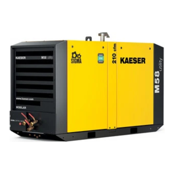
KAESER KOMPRESSOREN MOBILAIR M58utility Operator's Manual (254 pages)
Portable Rotary Screw Compressor
Brand:
KAESER KOMPRESSOREN
| Category:
Air Compressor
| Size: 6.05 MB
Table of Contents
Table of Contents
3
Regarding this Document Using this Document
13
Further Documents
13
Copyright
13
Symbols and Labels
13
Warnings
13
Tab. 1 Danger Levels and Their Definitions (Personal Injury)
13
Potential Damage Warnings
14
Other Alerts and Their Symbols
14
Tab. 2 Danger Levels and Their Definition (Damage to Property)
14
Technical Data Nameplate
16
Vehicle Identification Number
16
Options
16
Tab. 3 Nameplate
16
Air Treatment
17
Tool Lubricator
17
Air Distributor
17
Low Temperature Equipment
17
Tab. 4 Extract from the Options Label
17
Tab. 5 Optional Air Treatment Equipment
17
Tab. 6 Tool Lubricator Option
17
Tab. 7 Compressed Air Distributor Option
17
Equipment for Fire Hazard Areas
18
Automatic Engine Start/Stop
18
GSM/GPS Unit
18
Machine (Without Options)
18
Sound Pressure Level
18
Tab. 8 Low Temperature Equipment Options
18
Tab. 9 Optional Equipment for Fire Hazard Areas
18
Tab. 10 Automatic Engine Start/Stop
18
Tab. 11 GSM/GPS Unit
18
Tab. 12 Sound Pressure Level
18
Tightening Torque
19
Ambient Conditions
19
Tab. 13 Torques for M4-M8 Screws
19
Tab. 14 Torques for M10-M24 Screws
19
Tab. 15 Torque Cover Fixing Screws Oil Separator Tank
19
Tab. 16 Ambient Conditions
19
Additional Information According to the Machine's Operating Licence
20
Compressor
20
Working Gauge Pressure and Volumetric Flow Rate
20
Compressed Air Outlet
20
Safety Valves
20
Tab. 17 Working Pressure an Volumetric Flow (Installation of the Machine Within the EU)
20
Tab. 18 Working Pressure an Volumetric Flow (Installation of the Machine Outside of the EU)
20
Tab. 19 Compressed Air Distributor
20
Temperature
21
Cooling Oil Recommendation
21
Tab. 20 Safety Valve Opening Pressure
21
Tab. 21 Required Temperatures Readiness to Switch to LOAD Mode
21
Tab. 22 Airend Discharge Temperature
21
Tab. 23 Cooling Oil Recommendations
21
Cooling Oil Charge Quantity
22
Tab. 24 Cooling Oil Recommendation (Food Processing)
22
Tab. 25 Cooling Oil Charge Quantity
22
Engine
23
Engine Specification
23
Tab. 26 Kubota V 2403-CR Engine Specifications
23
Tab. 27 Engine Specifications
23
Oil Recommendation
24
Fuel Recommendation
24
Tab. 28 Engine Oil Recommendation
24
Tab. 29 Initial Engine Oil Quantity
24
Engine Coolant Recommendation
25
Tab. 30 Water Quality Parameters for Cooling Water
25
Fluid Volumes
26
Tab. 31 Initial Filling of Engine Water Cooler
26
Tab. 32 Fluid Volumes
26
Battery
27
Options
27
Air Treatment Options
27
Low Temperature Equipment
27
Tab. 33 Battery
27
Tab. 34 Road Breaker Lubricant Recommendation
27
Tab. 35 Interrelation between Compressed Air Treatment and Compressed Air Quality
27
Auxiliary Electrical Systems
28
GSM/GPS Unit
28
Tab. 36 Environmental Conditions, Low Temperature Equipment
28
Tab. 37 Power Supply Details
28
Tab. 38 Technical Data - Cooling Water Pre-Heating Device
28
Tab. 39 Battery Charger Specification
28
Tab. 40 GSM/GPS Unit
29
Safety and Responsibility Basic Instructions
30
Specified Use
30
Incorrect Use
30
User's Responsibilities
30
Observe Statutory and Universally Accepted Regulations
30
Determining Personnel
31
Complying with Inspection Schedules and Accident Prevention Regulations
31
Dangers
32
Safely Dealing with Sources of Danger
32
Tab. 41 Inspection Intervals According to Ordinance on Industrial Health and Safety
32
Safe Machine Operation
35
Organizational Measures
38
Danger Areas
38
Safety Devices
38
Tab. 42 Danger Areas
38
Safety Signs
39
Fig. 1 Location of Safety Signs (Outside)
39
Tab. 43 Safety Signs
40
Fig. 2 Location of Safety Signs (Inside)
41
Noise Control Requirements
42
Emergencies
42
Correct Actions in the Event of a Fire
42
Tab. 44 Safety Signs
42
Treating Injuries from Handling Operating Fluids/Materials
43
Warranty
43
Noise Emissions Warranty
44
Identifying the Effects of Improper Modifications
44
Environmental Protection
45
Design and Function Bodywork
46
Fig. 3 Overview of Bodywork
46
Machine Structure
47
Fig. 4 Left Side (Access Side), Panel Removed
47
Fig. 5 Right Side, Panels Removed
47
Fig. 6 Access Door (Operating Side), Open
48
Fig. 7 View from Above, Machine Roof Removed
49
Fig. 8 Underside of the Machine
49
Machine Function
50
Fig. 9 Machine Overview
50
Operating Modes and Control Mode
51
Machine Operating Modes
51
MODULATING Control
51
Safety Devices
52
Monitoring Functions with Shut-Down
52
Fig. 10 Stepless Regulation of Volumetric Flow (Standstill)
52
Further Safety Devices
53
Battery Isolating Switch
53
Fig. 11 Battery Isolating Switch
53
SIGMA CONTROL SMART Operator Panel
54
Fig. 12 SIGMA CONTROL SMART Operator Panel - Overview
54
Exhaust Gas After-Treatment
55
Engine Optimisation
55
Tab. 45 Instrument Panel Keys and Displays
55
Exhaust Gas Treatment System
56
Fig. 13 Principle of Treatment Devices
56
Regeneration of the Diesel Particulate Filter
57
Sealed Floor Pan
58
Options
58
Fig. 14 Position of Service Openings in the Closed Floor Pan
58
Air Treatment Options
59
Fig. 15 Compressed Air Options
59
Fig. 16 Tool Lubricator
60
Auxiliary Electrical Systems
61
Fig. 17 Principle Tool Lubricator
61
Low Temperature Equipment Options
62
Options for Operating in Fire Hazard Areas
62
Fig. 18 Service Work on the Machine Roof
62
Start/Stop/Automatic Options
63
GSM/GPS Unit
63
Installation and Operating Conditions
64
Ensuring Safety
64
Installation Conditions
64
Complying with Installation Conditions When Installing on a Truck Load Platform
65
Observing the Conditions of Stationary Installation
65
Fig. 19 Installation on a Truck Load Platform
65
Fig. 20 Minimum Distance from Excavations/Slopes and Walls
66
Installation
67
Ensuring Safety
67
Reporting Transport Damage
67
Mounting the Machine on the Truck Platform
67
Mounting the Machine Mounts/Rubber Pads on the Machine
67
Mounting the Machine on the Truck Platform
68
Have the "Remote on Contact" of the Automatic Start/Stop System Connected
68
Fig. 21 Mounting the Machine Mount/Rubber Pad
68
Electrical Connection of the Battery Charger
69
Initial Start-Up Ensuring Safety
70
Before Initial Start-Up (or Recommissioning)
70
Instructions to be Observed before Commissioning or Recommissioning
70
Special Measures for Re-Commissioning after Storage or De-Commissioning
71
Checking Installation and Operating Conditions
71
Tab. 46 Measures for Re-Commissioning the Compressor after a Long Period of Storage or De-Commissioning
71
Tab. 47 Installation Conditions Checklist
71
Low-Temperature Operation (Winter)
72
Starting Assistance
72
Fig. 22 Jumper Cable Connection Diagram
73
Starting up Low-Temperature Equipment
74
Commissioning Electrical Equipment
75
Fig. 23 Connect Auxiliary Electrical Systems
75
Operation
76
Ensuring Safety
76
Starting and Stopping
77
Fig. 24 Starting Instruments
77
Follow the Brief Operating Instructions
78
Fig. 25 Instrument Panel Keys and Indicators
78
Fig. 26 Brief Instructions on Starting Procedure
78
Commissioning the Machine
79
Fig. 27 Brief Instructions on Stopping Procedure
79
Starting the Machine
80
Fig. 28 "Battery Isolating Switch
80
Regulating the Shut-Off Valve
81
Setting the Compressed Air Discharge Pressure
82
Fig. 29 Control Line Shut-Off Valve
82
Fig. 30 Quick Access Adjustment Compressed Air Output Pressure
83
Fig. 31 Setting the Compressed Air Discharge Pressure
83
Shutting down the Machine
84
Shutting down in an Emergency
85
Refueling the Machine
86
Use the Specified Fuel Type
86
Fig. 32 Filling the Tank with the Correct Fuel Type
87
Tab. 48 Measures Required Should the Fuel Tank be Filled with the Incorrect Fuel Type
87
Filling the Fuel Tank at a Pump by Means of a Refueling Nozzle
88
Tab. 49 Fuel / Fuel Specification
88
Filling the Fuel Tank on a Construction Site by Means of a Canister
89
Confirming Alarm and Warning Messages
89
Confirming Alarm Messages
89
Confirming Warning Messages
90
Cleaning the Machine after Operation
90
Cleaning the Exterior of the Machine
91
Cleaning the Interior of the Machine
92
Tab. 50 Plug Sockets on the Exterior of the Machine
92
Tab. 51 High-Pressure Washer Setting
93
Operating the Options
94
Operating the Machine with the "Start-Stop Automatic" Option
94
Fig. 33 Make the "Start-Stop Automatic" Ready to Start
95
Operating the Tool Lubricator
96
Fig. 34 Setting the Tool Lubricator
96
Using the Low-Temperature Equipment
97
Fault Recognition and Rectification
98
Basic Instructions
98
Analysing SIGMA CONTROL SMART Messages
98
Alarm Messages on the Controller (Machine Off)
98
Tab. 52 Alarm Messages and Actions Concerning the Engine
99
Tab. 53 Alarm Messages and Actions Concerning the Compressor Unit
100
Tab. 54 Alarm Messages and Actions Concerning the Controller
100
Warning Messages on the Controller
101
Tab. 55 Alarm Messages and Troubleshooting in "General Faults
101
Tab. 56 Warning Messages and Measures Relating to the Engine
102
Tab. 57 Warning Messages and Measures Relating to the Compressor
102
Evaluating Engine Faults and Alarms
103
Engine Stops or Fails to Start
103
Tab. 58 General Warning Messages and Measures
103
Drive Engine Does Not Reach Full Speed
104
Drive Engine Knocking or Fails to Start
104
Tab. 59 Fault: "Engine Does Not Start or Stops
104
Tab. 60 Fault: "Engine Not Reaching Full Speed
104
Tab. 61 Fault: "Drive Engine Knocking or Fails to Start
104
Analysing Compressor Faults and Alarms
105
Working Pressure too High
105
Working Pressure too Low
105
Tab. 62 Fault: Working Pressure too High
105
Tab. 63 Fault: Working Pressure too Low
105
Pressure Relief Valve Blowing off
106
Machine Overheating
106
Tab. 64 Fault: Pressure Relief Valve Blowing off
106
Tab. 65 Fault: Machine Overheating
106
Too Much Oil Residue in the Compressed Air
107
Oil Flows from the Compressor Air Filter after Shutdown
107
High Moisture Content in the Compressed Air
107
Tab. 66 Alarm: "Too Much Oil Residue in the Compressed Air
107
Tab. 67 Alarm: "Oil Flows from the Compressor Air Filter after Shutdown
107
Tab. 68 Fault: High Moisture Content in the Compressed Air
107
10 Maintenance
108
Ensuring Safety
108
Tab. 69 Advise Others that the Machine Is Being Serviced
108
Note the Maintenance Messages on the Controller
109
Evaluating the Maintenance Message
109
Concluding the Maintenance
110
Maintenance Schedules
110
Logging Maintenance Work
110
Preventive Maintenance
110
Tab. 70 Maintenance Messages and Required Actions
110
Maintenance Tasks after Commissioning
111
Regular Maintenance Tasks
111
Tab. 71 Maintenace Tasks on the Machine after Commissioning
111
Tab. 72 Maintenance Intervals and Regular Maintenance Tasks
111
Tab. 73 Regular Machine Maintenance Tasks
115
Drive Engine Maintenance
116
Coolant Cooler Maintenance
116
Tab. 74 Regular Maintenance Task Options
116
Fig. 35 Checking the Coolant Level
117
Fig. 36 Recommended Mixture Ratio for Coolant
119
Tab. 75 Coolant Mixture Table
119
Fig. 37 Draining the Coolant from the Engine Coolant Cooler
120
Engine Air Filter Maintenance
121
Fig. 38 Cleaning the Dust Evacuator Valve
122
Fig. 39 Engine Air Filter Maintenance
122
Fig. 40 Service Cover Engine Air Filter
123
Fig. 41 Cleaning the Filter Element
123
Fuel System Maintenance
124
Fig. 42 Fuel System Maintenance
125
Fig. 43 Bleeding the Fuel System
125
Fig. 44 Warning Messages: Fuel Filter Water Level
126
Fig. 45 Emptying the Fuel Pre-Filter and Water Trap
127
Fig. 46 Changing the Fuel Pre-Filter Cartridge
128
Checking the Engine Oil Level
129
Fig. 47 Fuel Fine Filter Maintenance
129
Engine Oil Filling and Topping up
130
Fig. 48 Checking the Engine Oil Level
130
Changing the Engine Oil
131
Fig. 49 Draining the Engine Oil
132
Replace the Engine Oil Filter
133
Fig. 50 Change the Oil Filter
133
Drive Belt Maintenance
134
Fig. 51 Belt Guard Attachment
134
Fig. 52 Checking the Drive Belt Seating
135
Fig. 53 Manually Checking the Belt Tension
135
Fig. 54 Tension the Belt
136
Fig. 55 Replace the Drive Belt
137
Battery Maintenance
138
Fig. 56 Safety Signs - Warning Stickers on the Battery
138
Tab. 76 Starter Battery Charge Level
139
Change the Oil Separator Element
141
Checking the Fastening of the Fuel Tank
142
Fig. 57 Change the Oil Separator Element
142
Servicing the Components of the Emission After-Treatment System
143
Compressor Maintenance
143
Check the Cooling Oil Level
143
Cooling Oil Filling and Topping up
144
Fig. 58 Check the Cooling Oil Level
144
Changing the Cooling Oil
145
Fig. 59 Draining the Compressor Cooling Oil
146
Replacing the Compressor Oil Filter
147
Fig. 60 Change the Oil Filter
148
Oil Separator Tank Dirt Trap Maintenance
149
Fig. 61 Oil Separator Tank Dirt Trap Maintenance
149
Changing the Oil Separator Cartridge
150
Fig. 62 Changing the Oil Separator Cartridge
151
Compressor Air Filter Maintenance
152
Fig. 63 Compressor Air Filter Maintenance
153
Fig. 64 Cleaning the Filter Element
154
Fit the Flexible Pipe Connection
155
Fig. 65 Fit the Flexible Pipe Connection
155
Tab. 77 Dimensions of the Flexible Pipe Connection
155
Cleaning the Cooler
156
Cleaning the Compressor Cooler and Engine Radiator
156
Cleaning the Compressed Air After-Cooler
157
Fig. 66 Cleaning the Compressor Cooler and Engine Radiator
157
Checking Screw Connections
158
Fig. 67 Cleaning the Compressed Air After-Cooler
158
Maintenance of Rubber Sealing Strips
159
Check/Replace Hose Lines
160
Replace the Fuel Lines of the Drive Engine
160
Replace the Pressure Hoses of the Engine
160
Replace the Pressure Hoses of the Compressor
160
Draining Liquid Accumulation Within the Machine
161
Check Safety Functions
161
Check the EMERGENCY STOP Push Button
161
Have the Activating Pressure of the Safety Relief Valve Checked
162
Tab. 78 Relief Valve Activating Pressure
162
Having Excessive Temperature Shut-Down Function Checked
163
Maintenance for Optional Items
163
Tool Lubricator Maintenance
163
Tab. 79 Safety Shut-Down at Excessive Airend Discharge Temperature
163
Fig. 68 Tool Lubricator Maintenance
164
Centrifugal Separator Maintenance
165
Fig. 69 Cleaning the Condensate Drain
165
Spark Arrestor Cleaning
166
Fig. 70 Spark Arrestor Cleaning
167
Documenting Maintenance and Service Work
168
Tab. 80 Maintenance Log
168
11 Spares, Operating Materials, Service
169
Note the Nameplate
169
Ordering Consumable Parts and Operating Fluids/Materials
169
Tab. 81 Compressor Consumables
169
Kaeser Air Service
170
Service Addresses
170
Replacement Parts for Service and Repair
170
Tab. 82 Consumable Engine Parts
170
12 Decommissioning, Storage and Transport
205
Decommissioning
205
Temporary Decommissioning
205
Tab. 83 "Temporarily Decommissioned" Information Notice
205
Long-Term De-Commissioning and Storage
206
Tab. 84 "Long-Term Decommissioning and Storage" Checklist
206
Transport
207
Safety
207
Transport with a Crane
207
Tab. 85 Notice Text: "Long-Term Decommissioned and Storage
207
Transport with a Forklift Truck
208
Transporting the Machine as Load
209
Fig. 71 Transporting Using a Forklift Truck
209
Storage
210
Fig. 72 Guys to Secure the Freight
210
Disposal
211
Removing the Batteries
211
Draining Operating Fluids
212
Draining Condensate
212
Fig. 73 Battery Labelling
212
Tab. 86 Machine Fluids
212
Removing Filters/Filter Elements
213
Disposing of the Machine
213
Tab. 87 Machine Filters/Filter Elements
213
13 Annex
214
Identification
214
Identification of the Machine
214
Identification of the Drive Engine
214
Fig. 74 Identification of the Machine
214
Fig. 75 Identification of the Drive Engine
214
Identification of the Exhaust Gas After-Treatment System
215
Pipeline and Instrument Flow Diagram (P+I Diagram)
215
Fig. 76 Identification of the Exhaust Gas After-Treatment System
215
Dimensional Drawing
219
Electrical Diagram
221
Battery Charger Electrical Diagram
248
Fuel Circulation Diagram
252
Advertisement
Advertisement
Related Products
KAESER KOMPRESSOREN M170
KAESER KOMPRESSOREN SIGMA CONTROL SMART M114
KAESER KOMPRESSOREN MOBILAIR M27
KAESER KOMPRESSOREN SIGMA CONTROL SMART MOBILAIR M82
KAESER KOMPRESSOREN MOBILAIR M55 PE
KAESER KOMPRESSOREN M250
KAESER KOMPRESSOREN M43
KAESER KOMPRESSOREN CSD 102
KAESER KOMPRESSOREN CSD 122
KAESER KOMPRESSOREN CSD 82
KAESER KOMPRESSOREN Categories
Air Compressor
Controller
Blower
Dryer
Water Filtration Systems
More KAESER KOMPRESSOREN Manuals
Login
Sign In
OR
Sign in with Facebook
Sign in with Google
Upload manual
Upload from disk
Upload from URL