Sign In
Upload
Manuals
Brands
KAESER KOMPRESSOREN Manuals
Air Compressor
CSD 82
KAESER KOMPRESSOREN CSD 82 Manuals
Manuals and User Guides for KAESER KOMPRESSOREN CSD 82. We have
1
KAESER KOMPRESSOREN CSD 82 manual available for free PDF download: Service Manual
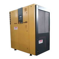
KAESER KOMPRESSOREN CSD 82 Service Manual (126 pages)
Screw Compressor
Brand:
KAESER KOMPRESSOREN
| Category:
Air Compressor
| Size: 2.06 MB
Table of Contents
Table of Contents
3
Regarding this Document
9
Handling the Document
9
Further Documents
9
Copyright
9
Symbols and Identifications
9
Warning Notices
9
Miscellaneous Notices and Symbols
10
Technical Specification
11
Weight
11
Temperature
11
Ambient Conditions
12
Pressure
12
Sound Pressure Level
12
Motor and Performance
12
Compressor Motor
12
Fan Motor
13
Cooling Oil
13
Recommended Cooling Oil
13
Cooling Oil Volumes
14
Power Supply
14
Power Supply Specifications
14
Water Cooling (Option K2)
16
Design Data
16
Cooling Water Quality
16
Internal Heat Recovery (Option W2 / W3)
17
Safety and Responsibility
19
Correct Use
19
Incorrect Use
19
User's Responsibilities
19
Safety Devices
20
Hazards
20
Danger from Electric Current
20
Danger from Released Spring Force
21
Danger from Released Compressed Air
21
Further Dangers
21
Warning Symbols
22
Emergencies
22
Fire Fighting
22
Cooling Oil
22
Environmental Protection
22
Design and Function
23
Machine Overview
23
Cabinet
23
Function
23
Options
25
Machine Mountings (Option H1)
25
Cooling Air Filter Mats (Option K3)
25
Water Cooling (Option K2)
25
Heat Recovery
25
Operating States and Control Modes
26
Operating States
26
Tasks of the Controller
26
Control Modes
26
Modulating Control (Option C1)
27
Safety Devices
27
SIGMA CONTROL Keys and Indicators
28
Installation and Operating Conditions
30
Ambient Conditions
30
Installation Conditions
30
Place of Installation and Space Required
30
Ventilation
31
Operating in a Compressed Air Network
32
Installation
33
Safety
33
Report any Transport Damage
33
Install the Compressed Air Connection
33
Electrical Connection
34
Options
34
Machine Fixing (Option H1)
34
Water Cooling Connection (Option K2)
34
Heat Recovery System Connection
35
Initial Start
37
Before Initial Start
37
Check Installation and Operating Conditions
37
Setting the Overload Protection Cut
37
Motor Protection Switch Setting
38
Pour Cooling Oil into the Inlet Port
38
Checking Direction of Rotation
39
Initial Start
39
Setting Network Pressure
39
Operation
40
Switching on and off
40
Switching on
40
Automatic Restart
40
Switching off
41
Switching off in an Emergency and Switching on Again
41
Remote on and off Switching
41
Switching on and off with the Clock
42
Acknowledging and Resetting Warning and Alarm Messages
42
Resetting Alarm Messages
42
Resetting Warning Messages
43
Event Recognition and Fault Rectification
44
Alarms (Machine Shut
44
Warning Messages (Yellow LED Blinking)
49
Miscellaneous Events (Faults)
52
Maintenance
54
Safety
54
Maintenance Schedule
55
Resetting Maintenance Interval Counters
55
Regular Maintenance Work
56
Oil Change Intervals
56
Regular Service Work
57
Cooler Maintenance
58
Air Cooling (Option K1)
58
Filter Mat Maintenance (Option K3)
58
Water Cooling Maintenance (Option K2)
59
Internal Heat Recovery Maintenance (Option W2 / W3)
60
Air Filter Maintenance
60
Filter Mat Maintenance (Control Cabinet Ventilator)
61
Electric Motor Maintenance
62
Checking the Coupling
63
Venting the Machine Manually
64
10.10 Checking and Topping up the Cooling Oil
65
10.10.1 Check Cooling Oil Level
65
10.10.2 Topping up the Cooling Oil
66
10.11 Changing the Cooling Oil
68
10.12 Oil Filter Maintenance
71
10.13 Checking the Pressure Relief Valve
72
10.14 Changing the Oil Separator Cartridge
73
10.15 Logging Maintenance Work
75
Spares, Operating Materials, Service
76
Note the Nameplate
76
Ordering Maintenance Parts and Operating Materials
76
Maintenance Contract
76
Service Addresses
76
Spare Parts for Service and Repair
76
Packing
83
Storage
83
Transporting
84
Disposal
84
Annex
85
Conformity
85
Diagrams and Drawings
85
Pipeline and Instrument Flow Diagram (P&I Diagrams)
85
Pipeline and Instrument Flow Diagram (Option C1)
91
Dimensional Drawing
97
Electrical Diagram
103
Advertisement
Advertisement
Related Products
KAESER KOMPRESSOREN CSD 102
KAESER KOMPRESSOREN CSD 122
KAESER KOMPRESSOREN AQUAMAT CF9
KAESER KOMPRESSOREN AQUAMAT CF19
KAESER KOMPRESSOREN AQUAMAT CF38
KAESER KOMPRESSOREN AQUAMAT CF75
KAESER KOMPRESSOREN AQUAMAT CF3
KAESER KOMPRESSOREN AQUAMAT CF6
KAESER KOMPRESSOREN CBC vac
KAESER KOMPRESSOREN EPC 1000-2-G
KAESER KOMPRESSOREN Categories
Air Compressor
Controller
Blower
Dryer
Water Filtration Systems
More KAESER KOMPRESSOREN Manuals
Login
Sign In
OR
Sign in with Facebook
Sign in with Google
Upload manual
Upload from disk
Upload from URL