Sign In
Upload
Manuals
Brands
JAI Manuals
Security Camera
TM-2030GE
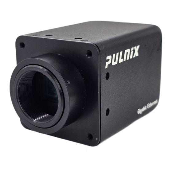
JAI TM-2030GE Manuals
Manuals and User Guides for JAI TM-2030GE. We have
2
JAI TM-2030GE manuals available for free PDF download: User Manual
JAI TM-2030GE User Manual (84 pages)
Progressive Scan Cameras
Brand:
JAI
| Category:
Security Camera
| Size: 4.36 MB
Table of Contents
Table of Contents
7
Table of Contents
8
List of Figures
11
1 Software Introduction
15
Scope of the Document
15
Related Documents
15
Gigabit Ethernet Camera Interface
15
Software Installation
16
Before Installing the Gige Series Camera-SDK Software
16
Installing the Software
16
Figure 1. Scanning for Drivers
16
Uninstalling the Software
17
Figure 2. Intel Pro Install Choices
17
Quick-Start
18
Figure 3. Change and Remove Buttons
18
Figure 4. Network Device Finder Window
18
Figure 5. Select Camera Window
19
2 Connectors
20
Power and Signals Connector
20
Figure 6. TM-2030GE Back Panel Connectors
20
Table 1. Hirose Connector, Pin Assignment
20
Ethernet
21
Figure 7. HR10A-10R-12P
21
Figure 8. Ethernet Gige Socket
21
3 Configuring the TM-2030GE Camera
22
Setup
22
Figure 9. Camera Interface Application Dialog Box
22
Figure 10. Advanced Configuration Window
23
To Use the Integrated Gige Camera Software
23
Configuring the Imager
24
Figure 11. Integrated Gige Camera Software
24
GUI Features
25
Configuring the Internal Frame Grabber
25
Modes
25
Check the Current Camera Setting
25
Exposure Control
26
Figure 12. Advanced Configuration - Port Communication
26
Figure 13. Exposure Control
26
Figure 14. Mode Control Pull-Down
27
Figure 15. Shutter Speed
27
Figure 16. Scan Mode
27
Gain Settings
28
Figure 17. Gain Setting Control
28
Figure 18. Continue Balancing Dialog Box
28
Offset Level
29
Figure 19. Gain Settings Checkbox Cleared
29
Figure 20. Offset Level
29
Look-Up Table
30
Memory
30
Figure 21. Look-Up Table
30
Free-Running Mode
31
Externally Triggered
31
Internally Triggered
31
Save/Restore Settings to Your Hard Disk
31
Figure 22. Memory Pages
31
White Balance Control (Color Versions Only)
32
Main Menu: "Option
32
Figure 23. White Balance Control Settings
32
Version
33
Exit
33
4 Signal Handling
33
Camera Inputs
33
Camera Outputs
33
GPIO Control Block
33
Figure 24. GE Camera GPIO Control Block
34
Figure 25. GPIO Look-Up Table
35
Figure 26. the GPIO Configuration
35
GPIO Label Table
36
Table 2. GPIO Look-Up Table Input Labels
36
Table 3. GPIO Look-Up Table Output Labels
37
Pulse Generators
38
Figure 27. Pulse Generator Page
38
5 Gige Series Camera Serial Commands
39
Table 4. TM/TMC-2030GE Command List
39
Table 5. Command Responses
41
6 Introduction
43
Software Installation
43
Before Installing Dual-Tap Accupixel Series Camera-Control Software
43
Installing the Software
43
Figure 28. the Setup Icon Installs Dual Tap Accupixel V 2.5.X.X
44
Figure 29. Accupixel Setup Screen
44
Uninstalling the Software
45
TM/TMC-2030GE Camera
45
Using the Gige Mode
45
Figure 30. the "Add or Remove Programs" Utility Can Uninstall Older Software
45
Figure 31. Back of the TM/TMC-2030GE
45
7 GUI Features
46
Figure 32. Main Dual Tap Accupixel Window
46
Operating the Control Software
47
Exposure Control
47
Figure 33. Continuous Mode Operates the Shutter Based on the Camera Settings
47
Figure 34. the Camera Offers Full Scan or Binning
47
Configuring Trigger Settings
48
Figure 35. to Use Programmable Shutter Speed, Select Programmable
48
Gain Control
49
Figure 36. Gain Is Being Set When the Auto Gain Box Appears Checked
49
Offset Voltage
50
Tap Selection
50
Video Depth
50
Figure 37. Auto Offset Is Checked Only While the Camera Sets the Command
50
Figure 38. Click on the Option Button to Set the Preferred Option
50
Figure 39. Use the Option Buttons to Select 8-Bit, 10-Bit, or 12-Bit Output
50
LUT (Look-Up Table)
51
Figure 40. Image Pre-Processing
51
Figure 41. Check "Enable Blemish Compensation" to Start Image Pre-Processing
51
Figure 42. Choose Either a Positive or Negative Image
51
Figure 43. Table Drop down Menu
52
Figure 44. Gamma.45 Imitates Human Eye Sensitivity When Creating an Image
52
Main Menu: "Option
53
Figure 45. the Setting Does Not Activate until the Send Knees Button Is Clicked
53
Figure 46. Please Contact JAI, Inc. for Password Access
53
Eeprom
54
8 Hardware Introduction
55
Product Description
55
Features
55
9 Installation
57
Getting Started
57
Unpacking Instructions
57
Components
57
Accessories and Options
57
Camera Setup
58
Heat Dissipation
58
Connector Pin Configurations
58
Figure 47. 12-Pin Connector Pinouts
58
Table 6. 12-Pin Connector
58
Power Supplies and Power Cable Setup
59
Figure 48. Gige Ethernet Connector
59
Figure 49. 12P-02S Interface Cable (Optional)
60
Attaching the Camera Lens
61
Adjustable Back-Focus
61
10 Operation
62
Progressive Scanning
62
Figure 50. Back Focus Set-Screw Locations
62
Full Scan Area 2X2 Binning
63
Preset Scan Area
63
Bayer Color Filter (Color Versions)
64
Color Filter Array
64
Figure 51. 2X2 Binning
64
Table 7. Scan Area Start Points
64
Bayer Color Filter Array (CFA)
65
Figure 52. Bayer Color Filter Response
65
Starting Pixel Configuration
66
Figure 53. Example of Color CCD CFA Pattern
66
Sync and Data
67
Figure 54. Example of TMC-2030GE (same as TM-2030GE)
67
Camera Functions
68
Interpolation Software
68
Color Interpolation
68
Dynamic Range Control
69
Programmable Look-Up Table (LUT) and Knee Control
69
Figure 55. Output and Blooming
69
External Sync and Pixel Locking
70
Electronic Shutter
70
Programmable Exposure-Continuous Mode
70
Asynchronous no Shutter Mode
71
Figure 56. External Trigger Timing
71
Asynchronous Programmable Exposure Mode
72
Figure 57. Asynchronous Programmable External Trigger
72
Pulse Width Control Mode
73
Figure 58. Pulse Width Control Trigger
73
Particle Imaging Velocimetry Fixed Exposure Mode
74
Figure 59. PIV Exposure Timing Table
74
PWC PIV Mode
75
Figure 60. PWC PIV Timing Table
75
Table 8. Asynchronous Mode Chart
75
Camera Timing Charts
76
Figure 61. Camera Timing Chart
76
Figure 62. Digital Data Output Order for Configuration
76
Figure 63. Field Video Timing--Continuous Mode
77
11 Troubleshooting
78
Problems and Solutions
78
Symptom: no Video
78
Symptom: Dark Video
78
Symptom: Non-Synchronized Video
78
Symptom: Video Does Not Display Properly
78
Symptom: Notebook Computer Driver Installation Problems
79
Information and Support Resources
79
12 Appendix
80
Specifications
80
Table 9. TM-2030GE Camera Specifications Table
80
Figure 64. Physical Dimensions
81
TM-2030GE Physical Dimensions
81
Figure 65. Spectral Response
82
Spectral Response
82
Advertisement
JAI TM-2030GE User Manual (64 pages)
Progressive Scan Cameras
Brand:
JAI
| Category:
Security Camera
| Size: 5.58 MB
Table of Contents
Table of Contents
5
Hardware Introduction
9
Product Description
9
Features
9
Installation
11
Getting Started
11
Unpacking Instructions
11
Components
11
Accessories and Options
11
Camera Setup
11
Heat Dissipation
11
Connector Pin Configurations
11
Power Supplies and Power Cable Setup
12
Figure 1. 12-Pin Connector Pinouts
12
Figure 2. Gige Ethernet Connector
12
Table 1 12-Pin Connector
12
Figure 3. 12P-02S Interface Cable (Optional)
13
Attaching the Camera Lens
14
Adjustable Back-Focus
14
Figure 4. Back Focus Set-Screw Locations
14
Operation
15
Progressive Scanning
15
Preset Scan Area
15
Full Scan Area 2X2 Binning
15
Bayer Color Filter (Color Versions)
16
Color Filter Array
16
Bayer Color Filter Array (CFA)
16
Figure 5. 2X2 Binning
16
Table 2 Scan Area Modes
16
Starting Pixel Configuration
17
Figure 6. Bayer Color Filter Response
17
Figure 7. Example of Color CCD CFA Pattern
17
Sync and Data
18
Camera Functions
18
Interpolation Software
18
Figure 8. Example of TMC-2030GE (same as TM-2030GE)
18
Color Interpolation
19
Dynamic Range Control
19
Figure 9. Output and Blooming
19
Programmable Look-Up Table (LUT) and Knee Control
20
External Sync and Pixel Locking
20
Electronic Shutter
20
Programmable Exposure-Continuous Mode
20
Asynchronous no Shutter Mode
20
Asynchronous Programmable Exposure Mode
21
Figure 10. External Trigger Timing
21
Pulse Width Control Mode
22
Figure 11. Asynchronous Programmable External Trigger
22
Figure 12. Pulse Width Control Trigger
22
Particle Imaging Velocimetry Fixed Exposure Mode
23
PWC PIV Mode
23
Figure 13. PIV Exposure Timing Table
23
Figure 14. PWC PIV Timing Table
23
Camera Timing Charts
24
Figure 15. Camera Timing Chart
24
Table 3 Asynchronous Mode Chart
24
Figure 16. Digital Data Output Order for Configuration
25
Figure 17. Field Video Timing--Continuous Mode
25
Functions and Operations
26
Gige Vision Standard Interface
26
Gige Vision-Aware Software
26
Recommended Network Configurations
26
Verified Network Interface Cards (Nics)
26
Video Data Rate (Network Bandwidth)
26
Disable Firewalls
27
Enabling Jumbo Frame
27
Setting Receive Descriptors
29
Interrupt Moderation Rate
30
Calculating and Setting Inter-Packet Delay
30
Confirm the Filter Driver Is Used
31
Configuring the Camera
33
Acquisition and Trigger Controls
33
Figure 18. Acquisition and Trigger Controls Category
33
Analogcontrols
34
Image Size Controls
35
Figure 19. Analogcontrols Category
35
Figure 20. Imagesizecontrol Category
36
Figure 21. Image Output Example
37
Image Preprocessing
38
LUT (Look up Table)
38
Figure 22. Lookup Table
38
Usersets
39
Figure 23. Usersets Category
39
Deviceinformation
40
Gigevisiontransportlayer
40
Persistent IP
40
Figure 24. Deviceinformation Category
40
Stream Channel Packet Size
41
Ipengine
41
Figure 25. Gigevisiontransportlayer Persistent IP
41
Figure 26. PLC LUT Diagram
42
Signalroutingblock
43
Figure 28. Signalroutingblock
43
Figure 27. PLC
44
Controlbits
45
PLC Lookuptable
46
Plcspecialconfigurations
47
Figure 31. PLC Special Configurations
48
Figure 32. Countersandtimerscontrols
48
Counters
49
Pulse Generators Controls
50
PLC Grabber Features
51
Ipengine Examples
51
Register Map
52
Troubleshooting
57
Problems and Solutions
57
Symptom: no Video
57
Symptom: Dark Video
57
Symptom: Non-Synchronized Video
57
Symptom: Notebook Computer Driver Installation Problems
57
Information and Support Resources
58
Appendix
59
Specifications
59
Table 4 TM-2030GE Camera Specifications Table
59
TM-2030GE Physical Dimensions
60
Figure 33. Physical Dimensions
60
Spectral Response
61
Figure 34. Monochrome Spectral Response
61
Figure 35. Color Spectral Response
61
Advertisement
Related Products
JAI TM-6710
JAI TMS-1402CL
JAI TM-1402CL
JAI TMC-4200CL
JAI TM-4200CL
JAI TM-1327GE Series
JAI TMC-773
JAI TMC-775
JAI TM-9730CL
JAI TMC-9730CL
JAI Categories
Security Camera
Digital Camera
Machine Vision Systems
Color Camera
CCD Cameras
More JAI Manuals
Login
Sign In
OR
Sign in with Facebook
Sign in with Google
Upload manual
Upload from disk
Upload from URL