Sign In
Upload
Manuals
Brands
iWave Manuals
Motherboard
iW-RainboW-G40D
User Manuals: iWave iW-RainboW-G40D Platform
Manuals and User Guides for iWave iW-RainboW-G40D Platform. We have
2
iWave iW-RainboW-G40D Platform manuals available for free PDF download: User Manual, Quick Start Manual
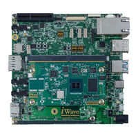
iWave iW-RainboW-G40D User Manual (89 pages)
Brand:
iWave
| Category:
Computer Hardware
| Size: 8 MB
Table of Contents
Table of Contents
4
Introduction
8
Purpose
8
Overview
8
List of Acronyms
8
Table 1: Acronyms & Abbreviations
8
Terminology Description
10
References
10
Table 2: Terminology
10
Architecture and Design
11
I.MX 8M Plus Q/QL/D SMARC Development Platform Block Diagram
11
Figure 1: I.MX 8M Plus Q/QL/D SMARC Development Platform Block Diagram
11
I.MX 8M Plus Q/QL/D SMARC Development Platform Features
12
SMARC MXM Connector
14
Figure 2: SMARC MXM Connector
14
SMARC PCB Edge Connector Pin Assignment
15
Table 3: SMARC MXM Connector Pin Assignment
15
Serial Interface Features
35
Debug UART Port
35
Figure 3: Data UART Header
35
RS232 UART Interface (Optional)
36
Figure 4: RS232 UART Header
36
Table 4: RS323 UART Header Pin out
36
Data UART Header
37
Figure 5: Data UART Header
37
Table 5: Data UART Header Pin out
37
High Speed Interface Features
38
Pcie Port
38
Figure 6: Pciex4 Connector
38
Table 6: Pciex4 Connector Pin out
39
Figure 7: M.2 Connector
41
Table 7: M.2 Connector Key B-Pcie Pinout
41
Secondary M.2 Interface (Optional)
45
Figure 8: Secondary M.2 Connector
45
Table 8: Secondary M.2 Connector Pinout
45
USB3.0 Host Interface
49
Figure 9: USB3.0 Host
49
Communication Interface Features
50
Dual Gigabit Ethernet Ports
50
USB2.0 Host Port
50
Figure 10: Dual Stack RJ45 Magjack
50
USB2.0 OTG Interface(Optional)
51
Figure 11: USB2.0 Host Port
51
SDIO Interface
52
Figure 12: USB2.0 OTG Port
52
CAN Interface
53
Figure 13: SDIO Port
53
Figure 14: CAN Header
54
Table 9: CAN0 Header Pinout
54
Table 10: CAN1 Header Pinout
54
Audio & Video Features
55
I2S Audio Interface
55
Figure 15: Audio in and out Ports
55
MIPI DSI Display
56
Figure 16: MIPI DSI Display Connector
56
Table 11: MIPI DSI Display Connector Pin out
57
LVDS Connector (Optional)
58
Figure 17: LVDS Display Connector
59
Table 12: LVDS Connector Pinout
59
HDMI Port
60
Figure 18: HDMI Port
60
MIPI CSI Camera
61
Figure 19: MIPI Camera Connect
61
Table 13: MIPI Camera Connector Pin out
61
Figure 20: MIPI Camera Connector
63
Table 14: MIPI CSI FPC Camera 36 Pin Connector Pinout
63
Table 15: MIPI CSI FPC Camera 40 Pin Connector Pinout (Optional)
65
LVDS1 Connector
67
Figure 21: LVDS1 Connector
67
Table 16: LVDS1 Connector Pinout
67
Additional Features
69
RTC Coin Cell Holder
69
SPI Flash
69
Figure 22: RTC Coin Cell Holder
69
QSPI Flash
70
Capacitive Touch Connector
70
Figure 23: Capacitive Touch Connector
70
Table 17: Capacitive Touch Connector
70
USB2.0 Header
71
Figure 24: USB2.0 Header
71
Display Backlight Power Header
72
Figure 25: Display Backlight Power Header
72
Table 18: USB2.0 Header
72
Table 19: Display Backlight Power Header
72
On Board Settings
74
Figure 26: SMARC on Board Switches
74
Table 20: Board Configuration Switch
74
Carrier Expansion Connectors
76
Figure 27: SMARC Expansion Connector
76
Table 21: Expansion Connector1 Pinout
77
Table 22: Expansion Connector2 Pinout
78
Technical Specification
81
Power Input Requirement
81
Figure 28: Power Jack
81
Power Output Specification
82
Table 23: Power Input Requirement
82
Table 24: Power Output Specification
82
Environmental Characteristics
83
Environmental Specification
83
Rohs Compliance
83
Electrostatic Discharge
83
Table 25: Environmental Specification
83
Mechanical Characteristics
84
I.MX 8M Plus Q/QL/D SMARC Carrier Board Mechanical Dimensions
84
Figure 29: Mechanical Dimension of I.MX 8M Plus Q/QL/D SMARC Carrier Board- Top View
84
Figure 30: Mechanical Dimension of I.MX 8M Plus Q/QL/D SMARC Carrier Board- Bottom View
85
Guidelines to Insert the SMARC SOM into Carrier Board
86
Figure 31: Mechanical Dimension of I.MX 8M Plus Q/QL/D SMARC Carrier Board- Side View
86
Figure 32: SOM Insertion Guideline
87
Ordering Information
88
Table 26: Orderable Product Part Numbers
88
Advertisement
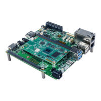
iWave iW-RainboW-G40D Quick Start Manual (16 pages)
Development Platform
Brand:
iWave
| Category:
Motherboard
| Size: 19 MB
Table of Contents
Quick Start Steps
5
Development Board
5
Quick View
6
Top View
6
Bottom View
6
Need more Help
15
Advertisement
Related Products
iWave iW-RainboW-G15S
iWave iW-RainboW-G21D
Iwave iW-RainboW-G15M
iWave iW-RainboW-G15D
iWave iW-RainboW-G25D
iWave iW-RainboW-G27M
iWave iW-RainboW-G20M
iWave iW-RainboW-G18D
iWave iW-RainboW-G20D
iWave iW-RainboW-G22D
iWave Categories
Motherboard
Computer Hardware
Single board computers
Control Unit
Microcontrollers
More iWave Manuals
Login
Sign In
OR
Sign in with Facebook
Sign in with Google
Upload manual
Upload from disk
Upload from URL