Sign In
Upload
Manuals
Brands
iWave Manuals
Motherboard
iW-RainboW-G18D
iWave iW-RainboW-G18D Development Board Manuals
Manuals and User Guides for iWave iW-RainboW-G18D Development Board. We have
2
iWave iW-RainboW-G18D Development Board manuals available for free PDF download: Linux User Manual, Hardware User's Manual
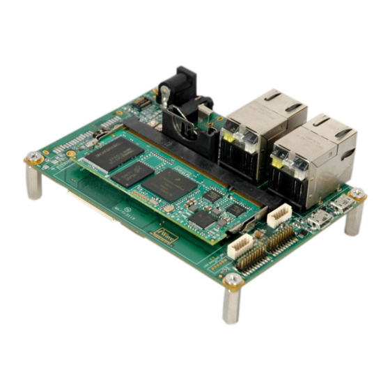
iWave iW-RainboW-G18D Hardware User's Manual (57 pages)
i.MX6UL/i.MX6ULL SODIMM Development Platform
Brand:
iWave
| Category:
Motherboard
| Size: 6 MB
Table of Contents
Table of Contents
4
1 Introduction
8
Purpose
8
Overview
8
List of Acronyms
8
Table 1: Acronyms & Abbreviations
8
Terminlogy Description
10
References
10
Table 2: Terminology
10
2 Architecture and Design
11
I.mx6Ul/I.mx6Ull SODIMM Carrier Board Block Diagram
11
Figure 1: I.mx6Ul/I.mx6Ull SODIMM Carrier Board Block Diagram
11
I.mx6Ul/I.mx6Ull SODIMM Carrier Board Features
12
SODIMM Connector
13
Figure 2: SODIMM Connector
13
Table 3: SODIMM Edge Connector Pin out
14
Serial Interface Features
26
Debug UART
26
Figure 3: Debug UART
26
Table 4: Debug UART Connector Pin out
26
Data UART Header
27
Figure 4: Data UART Header
27
Table 5: Data UART Header Pin out
27
Communication Features
28
Dual 10/100Mbps Ethernet
28
Figure 5: Dual 10/100Mbps RJ45 Magjacks
28
Table 6: RJ45 Magjack1 Pin out
29
Table 7: RJ45 Magjack2 Pin out
29
USB 2.0 Device
30
Figure 6: USB 2.0 Device Port
30
Table 8: USB 2.0 Device Connector Pin out
30
USB 2.0 Host
31
Figure 7: USB 2.0 Host Ports
31
Table 9: USB 2.0 Host 1 Connector (J5) Pin out
32
Table 10: USB 2.0 Host 2 Connector (J4) Pin out
32
SDHC Port
33
Figure 8: Micro SD Connector
33
Table 11: Micro SD Connector Pin out
33
CAN Port
34
Figure 9: CAN Header
34
Table 12: CAN Header Pin out
34
Audio/Video Features
35
Audio IN/OUT Jack
35
Figure 10: Audio IN/OUT Jack
35
Table 13: Audio In/Out Jack Pin out
35
RGB LCD with Touch
36
Figure 11: RGB LCD Connector
36
Table 14: 4.3" RGB LCD Connector Pin out
38
8Bit CMOS Camera Connector
39
Figure 12: Camera Connector
39
Table 15: Camera Connector Pin out
40
Additional Features
41
Boot Mode Switch
41
Figure 13: Boot Switch
41
Table 16: Boot Mode Settings
41
Reset Switch
42
Figure 14: Reset Switch
42
Power On/Off Switch
43
Figure 15: Power On/Off Switch
43
RTC Coin Cell Holder
44
Figure 16: RTC Coin Cell Holder
44
Table 17: RTC Coin Cell Holder Pin out
44
Expansion Header
45
Figure 17: Expansion Header
45
Table 18: Expansion Header Pin out
46
GPIO Header
47
Figure 18: GPIO Header
47
Table 19: GPIO Header Pin out
48
Optional Features
49
RTC Controller
49
JTAG Header
49
Figure 19: JTAG Header
49
Table 20: JTAG Header Pin out
50
3 Technical Specification
51
Electrical Characteristics
51
Power Input Requirement
51
Figure 20: Power Jack
51
Table 21: Power Jack Pin out
51
Table 22: Power Input Requirement
52
Environmental Characteristics
53
Environmental Specification
53
Rohs Compliance
53
Electrostatic Discharge
53
Table 23: Environmental Specification
53
Mechanical Characteristics
54
I.mx6Ul/I.mx6Ull SODIMM Carrier Board Mechanical Dimensions
54
Figure 21: Mechanical Dimension of SODIMM Carrier Board
54
Figure 22: Mechanical Dimension of SODIMM Carrier Board - Side View
54
4 Ordering Information
55
Table 24: Orderable Product Part Numbers
55
5 Appendix I
56
5. Appendix I
56
Figure 23: I.mx6Ul/I.mx6Ull SODIMM SOM Insertion Procedure
56
Figure 24: I.mx6Ul/I.mx6Ull SODIMM SOM Removal Procedure
56
Guidelines to Insert the I.mx6Ul/I.mx6Ull SODIMM SOM into Carrier Board
56
Guidelines to Remove the I.mx6Ul/I.mx6Ull SODIMM SOM from Carrier Board
56
Advertisement
iWave iW-RainboW-G18D Linux User Manual (58 pages)
i.MX6UL/ULL SODIMM Development platform
Brand:
iWave
| Category:
Motherboard
| Size: 1 MB
Table of Contents
Table of Contents
4
1 Introduction
7
Purpose
7
Scope
7
List of Acronyms
7
Table 1: Acronyms & Abbreviations
7
2 Board Support Package
9
Bsp Driver Details
9
BSP Supported Features
9
Driver Source Description
9
Table 2: Driver Source Path
9
Device Tree Source Description
11
Table 3: Device Tree Source
11
Bsp Yocto Compilation
12
Host Requirements
12
Host Setup
12
Host Package Installation
12
Setting up the Repo Utility
13
Yocto Project Setup
13
Cross-Compiler Build
14
Yocto Build
15
U-Boot
16
Linux Kernel
17
Bsp Standalone Compilation
17
U-Boot
18
Linux Kernel
19
Bsp Customization
21
Ethernet Selection in U-Boot
21
Default Linux Boot Logo
21
I2C Device on the Linux Image
21
Display Device on the Linux Image
22
3 Binary Programming
23
Mfg -Tool Programming
23
Requirements
23
Figure 1: Boot Device Memory Layout
23
MFG-Tool
24
Figure 2: Boot Switch Positions (before Programming)
24
Binary Programming
25
Figure 3: Platform Detection
25
Limitations
26
Figure 4: Binary Programming Succeed
26
Manual Sd Card Programming
27
Requirements
27
SD Card Partition
27
Binary Programming
30
4 U-Boot Testing and Boot Configuration
31
Basic Commands
32
Basic Device Tests
33
RAM Test
33
SD Test
34
NAND Flash Test
35
I2C Test
35
Ethernet Test
36
USB Test
39
Bmode Test
39
Environment Variables Settings
40
Micro SD Boot
40
NAND Boot
40
TFTP & NFS Boot
41
Optional Features Settings
41
5 Linux Peripheral Testing
42
Block Devices Test
42
SD/ USB Host/ NAND
43
USB OTG as Device
43
Figure 5: Otg Device Detection on Host Pc
44
Network Devices Test
45
Ethernet Test
46
CAN Test
48
Display Devices Test
49
LCD Test
49
Figure 6: Lcd Image Dump
49
PWM Brightness Test
50
Hid Devices Test
51
USB HID Devices
51
Touch Screen Test
52
Figure 7: Touch Screen Calibration Window
52
Uart Test
53
Rtc Test
54
Wdog Test
55
Multimedia Test
55
Camera Test
55
Audio Test
56
6 Appendix
57
Frequently Asked Question
57
Advertisement
Related Products
iWave iW-RainboW-G15S
iWave iW-RainboW-G21D
Iwave iW-RainboW-G15M
iWave iW-RainboW-G15D
iWave iW-RainboW-G25D
iWave iW-RainboW-G27M
iWave iW-RainboW-G20M
iWave iW-RainboW-G20D
iWave iW-RainboW-G22D
iWave iW-RainboW-G27D
iWave Categories
Motherboard
Computer Hardware
Single board computers
Control Unit
Microcontrollers
More iWave Manuals
Login
Sign In
OR
Sign in with Facebook
Sign in with Google
Upload manual
Upload from disk
Upload from URL