Sign In
Upload
Manuals
Brands
iWave Manuals
Motherboard
iW-RainboW-G20D
iWave iW-RainboW-G20D Manuals
Manuals and User Guides for iWave iW-RainboW-G20D. We have
1
iWave iW-RainboW-G20D manual available for free PDF download: Hardware User's Manual
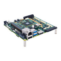
iWave iW-RainboW-G20D Hardware User's Manual (89 pages)
Brand:
iWave
| Category:
Motherboard
| Size: 11 MB
Table of Contents
Table of Contents
4
1 Introduction
8
Purpose
8
Overview
8
List of Acronyms
8
Table 1: Acronyms & Abbreviations
8
Terminlogy Description
10
References
10
Table 2: Terminology
10
2 Architecture and Design - Qseven Carrier Board
11
RZ/G1M/G1N Qseven Carrier Board Block Diagram
11
Figure 1: RZ/G1M/G1N Qseven Carrier Board Block Diagram
11
RZ/G1M/G1N Qseven Carrier Board Features
12
Qseven MXM Connector
14
Figure 2: Qseven MXM Connector
14
Table 3: Qseven MXM Connector Pin out
15
On Board Switches
31
Power ON/OFF Switch
31
Figure 3: Power ON/OFF Switch
31
Board Configuration Switch
32
Figure 4: Board Configuration Switch
32
Reset Switch
33
Figure 5: Reset Switch
33
Table 4: Board Configuration Switch
33
Serial Interface Features
34
Debug UART Port
34
Figure 6: Debug UART
34
Data UART Header
35
Figure 7: Data UART Header
35
Table 5: Data UART Header Pin out
35
High Speed Interface Features
36
USB3.0 Port0 (Host)
36
Figure 8: USB3.0 Host Port0
36
Table 6: Dual Stack USB 3.0 Connector Pin out (Bottom Port)
36
Pcie Channel0 Port
37
Figure 9: Pciex4 Connector
37
Table 7: Pciex4 Connector Pin out
38
Figure 10: Mini Pcie Connector
40
Table 8: Mini-Pcie Connector Pin out
40
SATA Channel0 Port (Optional)
42
Figure 11: SATA Connector
42
Table 9: SATA Connector Pin out
43
Communication Interface Features
44
Gigabit Ethernet Port
44
Figure 12: RJ45 Magjack
44
Table 10: RJ45 Magjack Pin out
45
USB2.0 Port0 (Host)
46
Figure 13: USB2.0 Port0 (Host)
46
Table 11: USB2.0 Port0 (Host) Connector Pin out
46
USB2.0 Port1 (OTG)
47
Figure 14: USB2.0 Port1 (OTG)
48
Table 12: USB2.0 Port1 (OTG) Connector Pin out
48
SDIO Port
49
Figure 15: SD/MMC Connector
49
Table 13: SD/MMC Connector Pin out
50
CAN0 Header
51
Figure 16: CAN Header
51
Table 14: CAN Header Pin out
51
Audio/Video Features
52
Audio in & out
52
Figure 17: Audio IN/OUT Jack
52
Table 15: Audio out Jack Pin out
53
Table 16: Audio in Jack Pin out
53
7" RGB LCD with Capacitive Touch
54
Figure 18: RGB LCD Connector
54
Table 17: 7" RGB LCD Connector Pin out
55
Table 18: Capacitive Touch Connector Pin out
56
Additional Features
57
SPI Flash
57
RTC Coin Cell Holder
57
Figure 19: Coin Cell Holder
57
Fan Header
58
Figure 20: Fan Header
58
Table 19: Fan Header Pin out
58
JTAG Header (Optional)
59
Figure 21: JTAG Header
59
Table 20: JTAG Header Pin out
60
SOM Expansion Connectors
61
Figure 22: SOM Expansion Connectors
61
Carrier Board Expansion Connectors
62
Figure 23: Carrier Board Expansion Connectors
62
Table 21: Expansion Connector3 Pin out
63
3 Architecture and Design - Camera Add-On Module
68
RZ/G1M/G1N Camera Add-On Module Block Diagram
68
Figure 24: RZ/G1M/G1N Camera Add-On Module Block Diagram
68
RZ/G1M/G1N Camera Add-On Module Features
69
Figure 25: Camera Add-On Module Expansion Connectors
69
Video Features
70
Analog Video/Tv in
70
Figure 26: Analog Video/Tv in JACK
70
Table 22: Analog Video/Tv in RCA Jack Pin out
70
8Bit CMOS Camera
71
Figure 27: 8Bit CMOS Camera Header
71
Table 23: Camera Connector Pin out
72
HDMI Output
73
Figure 28: HDMI Output
73
Table 24: HDMI Output Connector Pin out
73
HDMI Input (Optional)
74
16Bit CMOS Camera (Optional)
74
Communication Interface Features
75
CAN1 Header
75
Figure 29: CAN1 Header
75
Table 25: CAN1 Header Pin out
75
Serial Interface Features
76
Data UART RS232 Header
76
Figure 30: Data UART 2 Header
76
Table 26: Data UART 2 Header Pin out
76
High Speed UART RS232 Header
77
Figure 31: High Speed UART Header
77
Table 27: High Speed UART Header Pin out
77
4 Technical Specification
78
Electrical Characteristics
78
Power Input Requirement
78
Figure 32: Power Jack
78
Table 28: Power Jack Pin out
78
Power Output Specification
79
Table 29: Power Input Requirement
79
Table 30: Power Output Specification
79
Environmental Characteristics
80
Environmental Specification
80
Rohs Compliance
80
Electrostatic Discharge
80
Table 31: Environmental Specification
80
Mechanical Characteristics
81
RZ/G1M/G1N Qseven Carrier Board Mechanical Dimensions
81
Figure 33: RZ/G1M/G1N Qseven Carrier Board Mechanical Dimension - Top View
81
Figure 34: RZ/G1M/G1N Qseven Carrier Board Mechanical Dimension - Side View
81
RZ/G1M/G1N Camera Add-On Module Mechanical Dimensions
82
Guidelines to Insert the Qseven SOM into Carrier Board
82
Figure 35: RZ/G1M/G1N Camera Add-On Module Mechanical Dimension - Bottom View
82
Figure 36: Qseven SOM Insertion Procedure
82
5 Ordering Information
83
Table 32: Orderable Product Part Numbers
83
6 Appendix I
84
6. Appendix I
84
Camera Add-On Module Integration Procedure
84
Table 33: Camera Add-On Module Accessories
84
Figure 37: Insert Pan Head Screw
85
Figure 38: Tighten Metallic Hex Spacer
85
Figure 39: Insert Camera Add-On Module
86
Figure 40: Insert Non-Metallic Flat Washer
86
Figure 41: Insert Split Lock Washer
87
Figure 42: Tighten the Nut
87
8Bit CMOS Camera Connecting Procedure
88
Figure 43: Camera Connection
88
Figure 44: Camera Lens Cap
88
Advertisement
Advertisement
Related Products
iWave iW-RainboW-G15S
iWave iW-RainboW-G21D
Iwave iW-RainboW-G15M
iWave iW-RainboW-G15D
iWave iW-RainboW-G25D
iWave iW-RainboW-G27M
iWave iW-RainboW-G20M
iWave iW-RainboW-G18D
iWave iW-RainboW-G22D
iWave iW-RainboW-G27D
iWave Categories
Motherboard
Computer Hardware
Single board computers
Control Unit
Microcontrollers
More iWave Manuals
Login
Sign In
OR
Sign in with Facebook
Sign in with Google
Upload manual
Upload from disk
Upload from URL