Sign In
Upload
Manuals
Brands
Intel Manuals
Chassis
P4304 SFCN Series
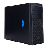
User Manuals: Intel P4304 SFCN Series Server Chassis
Manuals and User Guides for Intel P4304 SFCN Series Server Chassis. We have
1
Intel P4304 SFCN Series Server Chassis manual available for free PDF download: Service Manual
Intel P4304 SFCN Series Service Manual (92 pages)
Server Chassis
Brand:
Intel
| Category:
Chassis
| Size: 5 MB
Table of Contents
Safety Information
3
Preface
5
Table of Contents
7
Server Chassis Features
13
Figure 1. Chassis Front View for Fixed Hard Drive Configuration
13
Figure 2. Chassis Front View for Hot-Swap Hard Drive Configuration
13
Chassis Features
14
Table 1. Breakdown of Intel
14
Table 2. Intel Server Chassis P4000S Family Base Features
14
Component Identification
15
Figure 3. Internal Chassis View of Intel Server Chassis P4304XXSFCN
15
Figure 4. Internal Chassis View of Intel Server Chassis P4304XXSHCN
16
Figure 5. Internal Chassis View of Intel Server Chassis P4304XXSFEN
17
Figure 6. Internal Chassis View of Intel Server Chassis P4304XXSHEN
18
Figure 7. Internal Chassis View of Intel Server Chassis P4304XXSFDR
19
Figure 8. Internal Chassis View of Intel Server Chassis P4304XXSHDR
20
Front Panel
21
Figure 9. Front Panel Controls and Indicators
21
Table 3. Front Panel LED Functionality
21
Back Panel
22
Figure 10. Back Panel Layout (with Fixed Power Supply)
22
4X3.5'' Hard Drive Backplane
23
Figure 11. Back Panel Layout (with Hot-Swap Power Supply)
23
Figure 12. 4X3.5'' HSBP Board (Rear View)
24
Figure 13. 4X3.5'' HSBP Board Layout (Front View)
24
Hardware Installations and Upgrades
25
Before You Begin
25
Tools and Supplies Needed
25
System Reference
25
Removing and Installing the Chassis Cover
26
Removing the Chassis Cover
26
Figure 14. Removing the Chassis Cover
26
Installing the Chassis Cover
27
Removing and Installing the Front Bezel
27
Removing the Front Bezel
27
Figure 15. Installing the Chassis Cover
27
Installing the Front Bezel
28
Figure 16. Removing the Front Bezel
28
Figure 17. Installing the Front Bezel
28
Removing and Installing a DVD or CD-ROM Drive
29
Removing a DVD or CD-ROM Drive
29
Installing a DVD or CD-ROM Drive
29
Figure 18. Removing DVD or CD-ROM Drive
29
Figure 19. Re-Inserting Empty EMI Shield
29
Removing and Installing the Fixed HDD EMI Shield
30
Removing the Fixed HDD EMI Shield
30
Figure 20. Removing EMI Shield
30
Figure 21. Installing DVD or CD-ROM Drive
30
Installing the EMI Shield
31
Figure 22. Removing the EMI Shield
31
Figure 23. Installing the EMI Shield
31
Removing and Installing Fixed Hard Drive(S)
32
Removing Fixed Hard Drive(S)
32
Figure 24. Removing Fixed Hard Drives
32
Figure 25. Removing the 3.5'' HDD from Fixed HDD Tray
32
Installing Fixed Hard Drive(S)
33
Figure 26. Removing the 2.5'' HDD from Fixed HDD Tray
33
Figure 27. Reinstalling the HDD Carrier Tray
33
Figure 28. Removing Fixed Hard Drive
34
Figure 29. Securing the 3.5'' HDD on Fixed HDD Carrier Tray
34
Figure 30. Securing the 2.5'' HDD on Fixed HDD Carrier Tray
35
Figure 31. Inserting the HDD Carrier Tray
35
Removing and Installing 4X3.5'' Hot-Swap Hard Drive Cage Assembly
36
Removing 4X3.5'' Hot-Swap Hard Drive Cage with Backplane
36
Figure 32. Removing the 4X3.5'' HDD Cage
36
Installing 4X3.5'' Hot-Swap Hard Drive Cage with Backplane
37
Figure 33. Removing the EMI Shield
37
Figure 34. Installing the EMI Shield
38
Figure 35. Installing the 4X3.5'' Hot-Swap Hard Drive Cage
38
Removing and Installing 4X3.5'' Hot-Swap Backplane
39
Removing 4X3.5'' Hot-Swap Backplane
39
Figure 36. 4X3.5'' Hot Swap Backplane Cable Connections
39
Installing 4X3.5'' Hot-Swap Backplane
40
Figure 37. Removing 4X3.5'' Hot-Swap Backplane
40
Figure 38. Installing 4X3.5" Hot-Swap Backplane
40
Installing Hot-Swap Hard Drive
41
Installing 3.5" Hard Disk Drive
41
Figure 39. Removing the 2.5" HDD Interface Bracket from Carrier
41
Installing 2.5" Hard Disk Drive
42
Figure 40. Installing the 3.5" HDD into the Carrier
42
Figure 41. Removing the 2.5" HDD Interface Bracket from Carrier
42
Figure 42. Breaking off the Tab on the Bracket
43
Figure 43. Installing 2.5" HDD Interface Bracket into Carrier
43
Removing and Installing Airduct
44
Installing the Airduct
44
Figure 44. Installing the 2.5" HDD into Carrier
44
Removing the Airduct
45
Figure 45. Installing the Airduct
45
Figure 46. Removing the Airduct
45
Removing and Installing the Fixed Power Supply
46
Removing the Fixed Power Supply
46
Installing the Fixed Power Supply
46
Figure 47. Removing Fixed Power Supply
46
Installing an Additional Hot-Swap Power Supply Module
47
Figure 48. Installing Fixed Power Supply
47
Replacing a Hot Swap Power Supply Module
48
Figure 49. Removing Power Supply Filler Panel
48
Figure 50. Installing Additional Hot-Swap Power Supply Module
48
Figure 51. Removing Hot-Swap Power Supply Module from Chassis
48
Replacing the Power Distribution Board for 460W Psus
49
Figure 52. Installing Hot-Swap Power Supply Module into Chassis
49
Figure 53. Removing Hot-Swap Power Supply Module from Chassis
49
Figure 54. Loosening the Bracket with Power Distribution Board from Chassis
50
Figure 55. Removing the Bracket with Power Distribution Board from Chassis
50
Figure 56. Removing the Power Distribution Board from Bracket
51
Figure 57. Sliding the New Power Distribution Board in Bracket
51
Figure 58. Securing the New Power Distribution Board in Bracket
52
Figure 59. Sliding the Bracket into Power Supply Cage
52
Figure 60. Securing the Bracket into Power Supply Cage
53
Figure 61. Installing Hot-Swap Power Supply Module into Chassis
53
Removing and Installing the Rear Fixed Fan
54
Removing the Rear Fixed Fan
54
Installing the Rear Fixed Fan
54
Figure 62. Removing the Rear Fixed Fan
54
Removing and Installing the Front Fixed Fan
55
Removing the Front Fixed Fan
55
Figure 63. Installing the Rear Fixed Fan
55
Installing the Front Fixed Fan
56
Figure 64. Removing the Front Fixed Fan
56
Figure 65. Installing the Front Fixed Fan
57
Removing and Installing the PCI Card Guide
58
Removing PCI Card Guide
58
Installing PCI Card Guide
58
Figure 66. Removing the PCI Guard
58
Removing and Installing PCI Add-In Board(S)
59
Removing PCI Add-In Board(S)
59
Figure 67. Installing the PCI Guard
59
Installing PCI Add-In Board(S) for P4304XXSFCN and P4304XXSHCN
60
Figure 68. Removing the PCI Add-In Card
60
Figure 69. Preparing Chassis for Addition of PCI Add-In Board
61
Figure 70. Open the Back Panel PCI Add-In Board Retentaion Device
61
Installing Non-Full Length PCI Add-In Board(S) for P4304XXSFEN/P4304XXSHEN/P4304XXSFDR/P4304XXSHDR/P4304XXS FDN/P4304XXHDN
62
Figure 71. Installing PCI Add-In Board
62
Figure 72. Preparing Chassis for Addition of PCI Add-In Board
63
Figure 73. Open the Back Panel PCI Add-In Board Retentaion Device
63
Installing Full Length PCI Add-In Board(S) for P4304XXSFEN/P4304XXSHEN/P4304XXSFDR/P4304XXSHDR/P4304XXS FDN/P4304XXHDN
64
Figure 74. Installing PCI Add-In Board
64
Figure 75. Front Fixed System Fans
65
Figure 76. Assemblying the Fan in Fan Kit
65
Removing and Installing the Chassis Feet
66
Removing the Chassis Feet
66
Figure 77. Insert the Fan Assembly from Front of the Chassis
66
Figure 78. Installing the PCI Guard
66
Installing the Chassis Feet
67
Figure 79. Removing the Chassis Feet
67
Figure 80. Installing the Chassis Feet
67
Removing and Installing the Front Panel Tray
68
Removing the Front Control Panel Tray
68
Figure 81. Disconnecting the Cables from the Server Board
68
Installing the Fron Panel Tray
69
Figure 82. Sliding the Front Panel Tray out from the Chassis
69
Figure 83. Disconnecting the Cables from Front Panel Board
69
Figure 84. Connecting the Cables to the Front Panel Board
70
Figure 85. Installing the Front Panel Tray in Chassis
70
Replacing the Front Panel Board
71
Figure 86. Connecting the Cables to Server Board the Front Panel Tray in Chassis
71
Installing And/Or Removing a Server/Workstation Board
72
Figure 87. Removing the Front Panel Board
72
Figure 88. Removing and Installing the Cap on Front Panel Board
72
Figure 89. Installing the New Front Panel Board
72
Installing Alternate Serial Port
73
Connecting and Disconnecting Cables to or from Server Workstation Board
74
Connecting Cables to Server/Workstation Board
74
Removing Cables from Server/Workstation Board
74
Figure 90. Installing the Alternate Serial Port Knockout
74
Intel Remote Management Module 4
75
Mechanical Locks
75
Figure 91. RMM4 Knockout
75
Figure 92. Mechanical Locks
76
Technical Reference
77
Power Supply Specification
77
365-W Single Power Supply Input Voltage
77
365-W Single Power Supply Output Voltages
77
460-W Hot-Swap Power Supply Input Voltage
77
Table 4. Power Supply Output Voltages
77
460-W Hot-Swap Power Supply Output Voltages
78
550-W Single Power Supply Input Voltage
78
550-W Single Power Supply Output Voltages
78
System Environmental Requirements
78
Table 5. Power Supply Output Voltages
78
Table 6. Power Supply Output Voltages
78
Table 7. Environmental Requirements
78
Current Usage
79
Calculation Power Usage
79
Table 8. Power Usage Worksheet
79
Table 9. Power Usage Worksheet 2
80
Appendix A: Regulatory and Compliance Information
81
Appendix B: Safety Information
82
Appendix C: Installation/Assembly Safety Instructions
83
Appendix D: Getting Help
84
Warranty Information
84
Appendix E: Intel Server Issue Report Form
85
Appendix F: Warranty
90
Limited Warranty for Intel Chassis Subassembly Products
90
Extent of Limited Warranty
90
Warranty Limitations and Exclusions
91
Limitations of Liability
91
How to Obtain Warranty Service
91
Telephone Support
91
Returning a Defective Product
92
Advertisement
Advertisement
Related Products
Intel P4304XXMFEN2
Intel P4304XXMUXX
Intel P4000S Series
Intel P4304SC2SFEN
Intel P4304SC2SHDR
Intel P4304BT series
Intel P4304XXSHCN
Intel P4304XXSFCN
Intel P4304CR2LFJN
Intel P4304CR2LFJNL
Intel Categories
Motherboard
Computer Hardware
Server
Desktop
Server Board
More Intel Manuals
Login
Sign In
OR
Sign in with Facebook
Sign in with Google
Upload manual
Upload from disk
Upload from URL