Sign In
Upload
Manuals
Brands
Infineon Technologies Manuals
Controller
TC1796
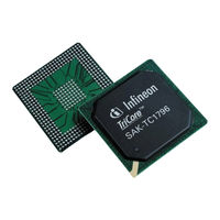
User Manuals: Infineon Technologies TC1796 TriCore
Manuals and User Guides for Infineon Technologies TC1796 TriCore. We have
1
Infineon Technologies TC1796 TriCore manual available for free PDF download: User Manual
Infineon Technologies TC1796 User Manual (2150 pages)
32-Bit Single-Chip Microcontroller
Brand:
Infineon Technologies
| Category:
Controller
| Size: 14 MB
Table of Contents
Table of Contents
9
System Units (Vol. 1 of 2)
40
Text Conventions
40
Reserved, Undefined, and Unimplemented Terminology
42
Register Access Modes
43
Abbreviations and Acronyms
44
System Architecture of the TC1796
47
TC1796 Block Diagram
48
Features
49
On-Chip Peripheral Units of the TC1796
53
Serial Interfaces
53
Asynchronous/Synchronous Serial Interfaces
54
High-Speed Synchronous Serial Interfaces
56
Micro Second Channel Interfaces
58
Multican Controller
60
Micro Link Serial Bus Interface
63
General Purpose Timer Array
65
Functionality of GPTA0 and GPTA1
66
Functionality of LTCA2
68
Analog-To-Digital Converters
69
Analog-To-Digital Converters (ADC0 and ADC1)
69
Fast Analog-To-Digital Converter Unit (FADC)
71
TC1796 Pin Definitions and Functions
73
TC1796 Pin Configuration
74
Pad Driver Classes Overview
96
Pull-Up/Pull-Down Behavior of the Pins
97
1 Introduction
40
About this Document
40
Related Documentations
40
2 CPU Subsystem
98
TC1796 Processor Subsystem
98
Central Processing Unit Features
99
CPU Diagram
100
Instruction Fetch Unit
101
Execution Unit
102
General Purpose Register File
103
Context Save Areas
104
Fast Context Switching
104
Implementation-Specific Features
104
Program Counter Register - PC
104
Reset System
104
Interrupt System
105
Trap System
105
TC1796 CPU Subsystem Registers
106
Core Special Function Registers (CSFR)
107
Implementation-Specific Core Special Function Registers
108
CPU Slave Interface (CPS) Registers
110
Implementation-Specific CPU Slave Interface Registers
111
CPU General Purpose Registers
112
Core Debug Registers
114
Implementation-Specific Core Debug Registers
115
Memory Protection Registers
117
Implementation-Specific Memory Protection Registers
120
PMI Features
121
Program Memory Interface (PMI)
121
Parity Protection for PMI Memories
122
PMI Registers
123
PMI Module Identification Register
124
PMI Control Register 0
125
PMI Control Register 1
126
PMI Control Register 2
127
Data Memory Interface (DMI)
128
DMI Features
128
CPU Buffer Write Operation
129
Dual-Ported Memory Operation
129
Parity Protection for DMI Memories
130
DMI Registers
131
DMI Register Description
132
Instruction Timing
137
Integer-Pipeline Instructions
138
Simple Arithmetic Instruction Timings
138
Multiply Instruction Timings
142
MAC Instruction Timings
143
Control Flow Instruction Timing
144
Address Arithmetic Timing
145
Load-Store Pipeline Instructions
145
Control Flow Instruction Timing
146
Load Instruction Timing
147
Store Instruction Timing
148
Floating Point Pipeline Timings
149
3 Clock System and Control
150
Overview
150
Clock Generation Unit
152
Main Oscillator Circuit
153
Oscillator Bypass Mode
154
Oscillator Run Detection
155
Oscillator Gain Control
156
Oscillator Control Register
157
Clock Source Control
159
Phase Looked Loop (PLL) Circuitry
159
PLL Parameters
161
PLL Clock Control and Status Register
165
Changing PLL Parameters
167
Setting up the PLL after Reset
167
Lock Detection
168
Loss-Of-Lock Recovery
168
Power-On Startup Operation
170
Module Power Management and Clock Gating
171
Module Clock Generation
172
Clock Control Register CLC
173
Fractional Divider Operation
178
Overview
178
Fractional Divider Operating Modes
181
Fractional Divider Register
184
Module Clock Register Implementations
188
Fractional Divider Register Implementations
189
System Clock Output Control
190
System Clock Fractional Divider Register
191
4 Reset and Boot Operation
193
Reset and Boot Overview
193
Reset Status and Control Registers
195
Reset Status Register
195
Reset Request Register
197
External Hardware Reset
199
Power-On Reset
199
Reset Operations
199
Software Reset
200
Watchdog Timer Reset
200
Debug System Reset
202
Module Reset Behavior
202
Booting Scheme
204
Normal Boot Options
206
Debug Boot Options
207
Addressing
208
Boot ROM
208
Program Structure
208
Initial State after Boot ROM Exit
211
Bootstrap Loader (BSL)
212
Bootstrap Loader Mode 1 - ASC Boot Via ASC0 Pins
213
Bootstrap Loader Mode 2 - CAN Boot Via CAN Pins
216
Alternate Boot Modes
220
Bootstrap Loader Mode 3 - ASC Boot Via CAN Pins
220
5 System Control Unit
223
Power Management
224
Power Management Overview
224
Power Management Control and Status Register, PMG_CSR
225
Idle Mode
227
Power Management Modes
227
Sleep Mode
228
States of TC1796 Units in Power Management Modes
229
Configuration Input Sampling
230
External Request Unit (ERU)
231
Input Channel
232
Output Channel
234
External Request Unit Implementation
236
External Request Unit Registers
238
FPU Interrupts
257
Special System Interrupts
257
External Interrupts
258
Flash Interrupt
258
SRAM Parity Control
259
Parity Error Trap Registers
261
Functional Description
263
Pad Driver Temperature Compensation Control
263
Temperature Compensation Registers
266
Die Temperature Sensor
270
GPTA1 Input IN1 Control
271
Pad Test Mode Control
272
Pad Test Mode Enabling
273
Pad Test Mode Registers
273
Emergency Stop Output Control for GPTA and MSC
279
GPTA Output Emergency Control in the GPIO Ports
280
MSC Emergency Control Selection
280
Emergency Stop Register
281
Analog Input 7 Testmode
282
SCU Registers and Address Map
283
Miscellaneous SCU Registers
286
SCU Control Register
286
SCU Status Register
289
Device Identification Registers
291
6 On-Chip System Buses and Bus Bridges
294
Overview
295
Program and Data Local Memory Buses
295
Address Alignment Rules
296
Atomic Transfers
296
Block Transfers
296
Reaction of a Busy Slave
296
Single Transfers
296
Transaction Types
296
LMB Basic Operation
297
Basic Operation
298
LMB Bus Arbitration
298
Local Memory Bus Controller Units
298
LMB Bus Default Master
299
LMB Bus Error Handling
299
DLMB and PLMB Bus Registers
300
Functional Overview
308
Local Memory to FPI Bus Interface (LFI Bridge)
308
LFI Register
309
Overview
312
System and Remote Peripheral Bus
312
Bus Transaction Types
314
Reaction of a Busy Slave
314
Address Alignment Rules
315
FPI Bus Basic Operations
315
Arbitration on the Remote Peripheral Bus
317
Arbitration on the System Peripheral Bus
317
FPI Bus Arbitration
317
FPI Bus Control Units (SBCU and RBCU)
317
FPI Bus Error Handling
318
Starvation Prevention
318
Clock Management
320
Address Triggers
321
BCU Debug Support
321
Grant Triggers
322
Signal Status Triggers
322
Combination of Triggers
323
BCU Breakpoint Generation Examples
324
SBCU and RBCU Registers
327
BCU Control Registers
329
BCU Error Registers
331
OCDS Registers
335
BCU Service Request Control Register
351
Boot ROM
352
7 Program Memory Unit
352
Program & Data Flash Memory
353
Program Flash Overview
355
Data Flash Overview
358
User Configuration Blocks Overview
360
Basic Flash Operating Modes
362
Read Mode
362
Command Mode
363
Page Mode
364
Command Sequence Definitions
365
Enter Page Mode Command
366
Reset-To-Read Command
366
Load Page Buffer Command
367
Write
369
Write User Configuration
370
Erase Sector Command
371
Erase User Configuration Block Command
373
Disable Write Protection Command
374
Disable Read Protection Command
375
Resume Protection Command
375
Clear Status Command
376
Data Flash and EEPROM Emulation
377
Read and Write Protection
378
User Configuration Block Definitions
378
Write and OTP Protection for PFLASH
381
Read Protection for PFLASH and DFLASH
383
Password Check Control
384
Dynamic Error Correction
385
Error Correction and Margin Control
385
Margin Check Control
386
Flash Interrupt Generation and Control
387
Flash Power Supply, Power Saving and Reset
389
Power Supply
389
Shut-Down Mode
389
Sleep Mode
389
Reset Control
390
Flash Registers
391
Flash and PMU Module Identification Registers
392
Flash Status Register
394
Margin Control Registers
402
Flash Configuration Register
404
Protection Configuration Registers
410
Emulation Interface
412
8 Data Memory Unit
413
DLMB/PLMB Interfaces
414
Sbram
414
Sram
414
Data Access Overlay Functionality
415
Parity Protection for DMU Memories
415
Access Performance
419
Emulation Memory Overlay
419
Internal Overlay
419
Region Priority
419
Switching between Internal and Emulation Memory Overlay
419
Data Read Buffer
420
Program Local Memory Bus Interface (LMI)
420
DMU Registers
422
How to Read the Address Maps
431
9 Memory Maps
431
Contents of the Segments
434
Address Map of the FPI Bus System
436
Segments 0 to 14
436
Segment 15
440
Address Map of the Program Local Memory Bus (PLMB)
445
Address Map of the Data Local Memory Bus (DLMB)
449
Memory Module Access Restrictions
452
10 General Purpose I/O Ports and Peripheral I/O Lines
453
Basic Port Operation
454
Port Register Description
457
Port Input/Output Control Registers
459
Pad Driver Mode Register
462
Port Output Register
465
Port Output Modification Register
466
Emergency Stop Register
468
Port Input Register
469
Port 0 Configuration
470
Port 0 Function Table
471
Port 0 Registers
474
Port 0 Pad Driver Mode Register and Pad Classes
475
Port 0 Software Configuration Selection
476
Reserved SWOPT Bits of SCU_SCLIR Register
477
Port 1
478
Port 1 Configuration
478
Port 1 Function Table
479
Port 1 Registers
482
Port 1 Pad Driver Mode Register and Pad Classes
483
Port 2
484
Port 2 Configuration
484
Port 2 Function Table
485
Port 2 Output Modification Register
489
Port 2 Output Register
489
Port 2 Registers
489
Port 2 Emergency Stop Register
490
Port 2 Input Register
490
Port 2 Input/Output Control Register 0
490
Port 2 Pad Driver Mode Register and Pad Classes
491
Port 3
492
Port 3 Configuration
492
Port 3 Function Table
493
Port 3 Registers
497
Port 3 Pad Driver Mode Register and Pad Classes
498
Port 4
499
Port 4 Configuration
499
Port 4 Function Table
500
Port 4 Registers
503
Port 4 Pad Driver Mode Register and Pad Classes
505
Port 5
506
Port 5 Configuration
506
Port 5 Function Table
507
Port 5 Input Register
509
Port 5 Output Modification Register
509
Port 5 Output Register
509
Port 5 Registers
509
Port 5 Pad Driver Mode Register and Pad Classes
510
Port 6 Configuration
511
Port 6 Function Table
512
Port 6 Registers
515
Port 6 Output Register
515
Port 6 Output Modification Register
515
Port 6 Input Register
515
Port 6 Pad Driver Mode Register and Pad Classes
516
Port 7
517
Port 7 Configuration
517
Port 7 Function Table
518
Port 7 Registers
520
Port 7 Output Register
520
Port 7 Output Modification Register
520
Port 7 Input Register
520
Port 7 Pad Driver Mode Register and Pad Classes
521
Port 8
522
Port 8 Configuration
522
Port 8 Function Table
523
Port 8 Register
525
Port 8 Output Register
525
Port 8 Output Modification Register
525
Port 8 Input Register
525
Port 8 Emergency Stop Register
525
Port 8 Pad Driver Mode Register and Pad Classes
526
Port 9
527
Port 9 Configuration
527
Port 9 Function Table
528
Port 9 Register
530
Port 9 Output Register
530
Port 9 Output Modification Register
530
Port 9 Input/Output Control Register 8
531
Port 9 Input Register
531
Port 9 Emergency Stop Register
531
Port 9 Pad Driver Mode Register and Pad Classes
532
Port 10 (Hardware Select Inputs)
533
Port 10 Configuration
533
Port 10 Registers
534
Port 10 Input Register
534
Dedicated I/O Lines for SSC0 and SSC1
535
Dedicated Peripheral I/O Lines
535
LVDS Outputs of MSC0 and MSC1
537
11 Peripheral Control Processor (PCP)
538
Peripheral Control Processor Overview
538
PCP Architecture
539
PCP Processor
540
FPI Bus Interface
541
PCP Code Memory
541
PCP Parameter RAM
541
PCP Interrupt Control Unit and Service Request Nodes
542
General Purpose Register Set of the PCP
543
PCP Programming Model
543
Register R0
544
Registers R1, R2, and R3
544
Registers R4 and R5
544
Register R6
545
Register R7
546
Context Models
548
Contexts and Context Models
548
Context Save Area
551
Context Restore Operation for CR6 and CR7
554
Context Save Operation for CR6 and CR7
558
Context Save Optimization
561
Initialization of the Contexts
561
Channel Programs
562
Channel Restart Mode
562
Channel Resume Mode
563
Channel Invocation and Context Restore Operation
565
PCP Initialization
565
PCP Operation
565
Channel Exit and Context Save Operation
566
Normal Exit
566
Error Condition Channel Exit
567
Debug Exit
568
Issuing Service Requests to CPU or PCP
569
PCP Interrupt Operation
569
PCP Interrupt Control Unit
570
PCP Service Request Nodes
570
Issuing PCP Service Requests
571
Service Request on EXIT Instruction
572
Service Request on Suspension of Interrupt
572
Queue Full Operation
573
Service Request on Error
573
Enforced PRAM Partitioning
575
PCP Error Handling
575
Channel Watchdog
576
Instruction Address Error
576
Invalid Opcode
576
DMA Primitives
577
Instruction Set Overview
577
Load and Store
578
Arithmetic and Logical Instructions
579
Bit Manipulation
581
Flow Control
581
Addressing Modes
582
FPI Bus Addressing
582
Bit Addressing
583
Flow Control Destination Addressing
583
PRAM Addressing
583
Access to the PCP Control Registers
585
Access to the PRAM
585
Accessing PCP Resources from the FPI Bus
585
Access to the CMEM
586
Debugging the PCP
587
PCP Registers
589
Module Identification Register, PCP_ID
591
PCP Clock Control Register, PCP_CLC
592
PCP Control and Status Register, PCP_CS
593
PCP Error/Debug Status Register, PCP_ES
596
PCP Interrupt Control Register, PCP_ICR
598
PCP Interrupt Threshold Register, PCP_ITR
600
PCP Interrupt Configuration Register, PCP_ICON
601
PCP Stall Status Register, PCP_SSR
603
PCP Service Request Control Registers, PCP_SRC[1:0]
604
PCP Service Request Control Registers, PCP_SRC[3:2]
605
PCP Service Request Control Registers, PCP_SRC[8:4]
606
PCP Service Request Control Registers, PCP_SRC[11:9]
607
Instruction Codes and Fields
609
PCP Instruction Set Details
609
Conditional Codes
610
Instruction Fields
611
Counter Operation for COPY Instruction
614
Counter Operation for BCOPY Instruction
615
Divide and Multiply Instructions
616
ADD, 32-Bit Addition
617
BCOPY, DMA Operation
618
AND, 32-Bit Logical and
619
CHKB, Check Bit
620
CLR, Clear Bit
620
COMP, 32-Bit Compare
621
COPY, DMA Instruction
622
DEBUG, Debug Instruction
623
DINIT, Divide Initialization Instruction
624
DSTEP, Divide Instruction
625
INB, Insert Bit
625
EXIT, Exit Instruction
626
JC, Jump Conditionally
627
JL, Jump Long Unconditional
628
LD, Load
628
LDL, Load 16-Bit Value
630
Multiply Initialization Instruction
630
MOV, Move Register to Register
631
Multiply Instructions
632
NEG, Negate
633
NOP, no Operation
633
NOT, Logical NOT
633
OR, Logical or
634
PRI, Prioritize
635
PRAM Bit Operations
636
RL, Rotate Left
637
RR, Rotate Right
637
SET, Set Bit
638
SHL, Shift Left
638
SHR, Shift Right
639
ST, Store
640
SUB, 32-Bit Subtract
641
XCH, Exchange
642
XOR, 32-Bit Logical Exclusive or
643
Flag Updates of Instructions
644
Instruction Timing
645
Channel Entry Table
649
Initial PC of a Channel Program
649
Programming of the PCP
649
Channel Resume
650
Channel Management for Small and Minimum Contexts
651
Unused Registers as Globals or Constants
651
Code Reuse Across Channels (Call and Return)
652
Dispatch of Low Priority Tasks
652
Case-Like Code Switches (Computed Go-To)
653
COPY Instruction
653
Simple DMA Operation
653
BCOPY Instruction (Burst Copy)
654
Notes on PCP Configuration
655
PCP Programming Notes and Tips
655
General Purpose Register Use
656
Control of Channel Priority (CPPN)
657
Dynamic Interrupt Masking
657
Use of Channel Interruption
657
Implementing Divide Algorithms
659
Implementing Multiply Algorithms
660
Implementation of the PCP in the TC1796
662
Parity Protection for PCP Memories
662
PCP Memories
662
PCP Reset Operation
663
BCOPY Instruction
664
12 Direct Memory Access Controller
665
DMA Controller Kernel Description
666
Features
667
Definition of Terms
668
DMA Principles
669
DMA Channel Functionality
670
Shadowed Source or Destination Address
670
DMA Channel Request Control
674
DMA Channel Operation Modes
675
Error Conditions
679
Channel Reset Operation
680
Transfer Count and Move Count
681
Circular Buffer
683
Transaction Control Engine
684
Bus Switch
685
Hard-Suspend Mode
687
On-Chip Debug Capabilities
687
Soft-Suspend Mode
687
Break Signal Generation
688
Trace Signal Generation
689
Channel Interrupts
691
Interrupts
691
Transaction Lost Interrupt
693
Move Engine Interrupts
694
Wrap Buffer Interrupts
696
Interrupt Request Compressor
697
Pattern Detection
698
Pattern Compare Logic
699
Pattern Detection for 8-Bit Data Width
700
Pattern Detection for 16-Bit Data Width
701
Pattern Detection for 32-Bit Data Width
702
Access Protection
704
DMA Module Kernel Registers
706
System Registers
709
General Control/Status Registers
715
Move Engine Registers
733
Channel Control/Status Registers
740
Channel Address Registers
752
DMA Module Implementation
755
DMA Request Wiring Matrix
756
Access Protection Assignment
762
Implementation-Specific DMA Registers
767
Clock Control Register
769
DMA Service Request Control Registers
770
MLI Service Request Control Registers
771
System Interrupt Service Request Control Register
772
DMA Controller Address Map
773
Functional Description
774
Memory Checker Module
774
Registers
775
Memory Checker Registers
776
13 LMB External Bus Unit
779
Block Diagram
780
Data Bus, D[31:0]
781
EBU Interface Signals
781
Address Bus, A[23:0]
782
Burst Flash Clock Output/Input, BFCLKO/BFCLKI
782
Chip Selects, CS[3:0], CSCOMB
782
Read/Write Control Lines, RD, RD/WR and MR/W
782
Address Valid, ADV
783
Byte Controls, BC[3:0]
783
Burst Address Advance, BAA
784
Bus Arbitration Signals, HOLD, HLDA, and BREQ
784
EBU Power Supply
784
Wait Input, WAIT
784
Arbitration Signals and Parameters
785
External Bus Arbitration
785
External Bus Modes
785
Arbiter Mode Arbitration Mode
788
Arbitration Modes
788
No Bus Arbitration Mode
788
Sole Master Arbitration Mode
788
Participant Mode" Arbitration Mode
792
Arbitration Input Signal Sampling
795
Locking the External Bus
795
Reaction to an PLMB Access to the External Bus
796
Pending Access Time-Out
797
Disabled
798
Emulation Mode
798
External Boot Mode
798
Start-Up/Boot Process
798
Boot Process
799
Boot Configuration Value
801
Master Mode Operation
803
External Memory Regions
804
Chip Select Control
806
Address Comparison
808
Access Parameter Selection
813
Little-/Big-Endian Access Modes
814
PLMB Bus Width Translation
815
Address Alignment During Bus Accesses
816
Data Read Buffer
817
PLMB Data Buffering
817
Code Prefetch Buffer
818
Data Write Buffer
818
Address Phase (AP)
819
Standard Access Phases
819
Command Delay Phase (CD)
821
Command Phase (CP)
821
Data Hold Phase (DH)
823
Burst Phase (BP)
824
Recovery Phase (RP)
825
Multiplication Factor for Access Phase Length
827
Asynchronous Read/Write Accesses
828
Signal List
828
Demultiplexed Device Configurations
829
Programmable Parameters
831
Standard Asynchronous Access Phases
831
Accesses to Demultiplexed Devices
833
Dynamic Command Delay and Wait State Insertion
835
External Extension of the Command Phase by WAIT
835
Interfacing to INTEL-Style Devices
839
Interfacing to Motorola-Style Devices
841
Burst Mode Read Accesses
843
Signal List
843
Burst Flash Memory Configurations
844
Burst Mode Access Phases
846
Programmable Parameters
846
BFCLKO Output
849
Support for Two Burst Flash Device Types
849
BFCLKI Input and Burst Flash Clock Feedback
850
Burst Length Control
851
Control of ADV and BAA Delays During Burst Flash Access
851
Burst Flash Access Cycle
852
External Cycle Control Via the WAIT Input
853
Wait for Page Load Mode
854
Terminate and Start New Burst Mode
855
Termination of a Burst Mode Read Access
856
EBU Registers
857
Identification Register, ID
859
Clock Control Register, CLC
860
Configuration Register, con
861
Burst Flash Control Register, BFCON
864
Address Select Register, Addrselx
868
Bus Configuration Register, Busconx
870
Bus Access Parameter Register, Busapx
875
Emulator Address Select Register, EMUAS
879
Emulator Bus Configuration Register, EMUBC
880
Emulator Bus Access Parameter Register, EMUBAP
884
Emulator Overlay Register, EMUOVL
888
Test/Control Configuration Register, USERCON
889
14 Interrupt System
890
Overview
890
Service Request Control Registers
892
Service Request Nodes
892
General Service Request Control Register Layout
893
Enable Bit (SRE)
894
Request Set and Clear Bits (SETR, CLRR)
894
Service Request Flag (SRR)
895
Type-Of-Service Control (TOS)
895
Service Request Priority Number (SRPN)
896
ICU Interrupt Control Register (ICR)
897
Interrupt Control Unit (ICU)
897
Interrupt Control Units
897
Operation of the Interrupt Control Unit (ICU)
899
PCP Interrupt Control Unit (PICU)
900
Arbitration Process
901
Controlling the Number of Arbitration Cycles
901
Controlling the Duration of Arbitration Cycles
902
Entering an Interrupt Service Routine
902
Exiting an Interrupt Service Routine
903
Interrupt Vector Table
904
Spanning Interrupt Service Routines Across Vector Entries
907
Usage of the TC1796 Interrupt System
907
Configuring Ordinary Interrupt Service Routines
908
Interrupt Priority Groups
908
Splitting Interrupt Service Across Different Priority Levels
909
Using Different Priorities for the same Interrupt Source
910
External Interrupts
911
Interrupt Priority 1
911
Software-Initiated Interrupts
911
Service Request Node Table
912
External NMI Input
914
Non-Maskable Interrupt
914
Phase-Locked Loop NMI
914
Watchdog Timer NMI
914
SRAM Parity Error NMI
915
NMI Enable
916
NMI Status Register
916
Operation
918
Overview
918
15 System Timer
918
Resolution and Ranges
921
Compare Register Operation
922
Compare Match Interrupt Control
923
Kernel Registers
924
General Module Register
926
Timer/Capture Registers
928
Compare Registers
932
Interrupt Registers
935
16 Watchdog Timer
939
Watchdog Timer Overview
939
Features of the Watchdog Timer
940
The Endinit Function
941
Watchdog Timer Operation
943
WDT Register Overview
944
Operating Modes of the Watchdog Timer
945
Disable Mode
946
Normal Mode
946
Time-Out Mode
946
Prewarning Mode
947
Password Access to WDT_CON0
948
Modify Access to WDT_CON0
949
Term Definitions for WDT_CON0 Accesses
950
Detailed Descriptions of the WDT Modes
951
Time-Out Mode Details
951
Normal Mode Details
952
Disable Mode Details
953
Prewarning Mode Details
954
WDT Operation During Power-Saving Modes
955
WDT Operation in OCDS Suspend Mode
955
Determining WDT Periods
956
Time-Out Period
956
Normal Period
958
WDT Period During Power-Saving Modes
959
Handling the Watchdog Timer
960
System Initialization
960
Re-Opening Access to Critical System Registers
961
Servicing the Watchdog Timer
961
Handling the User-Definable Password Field
962
Determining the Required Values for a WDT Access
965
Watchdog Timer Registers
966
Watchdog Timer Control Register 0
967
Watchdog Timer Control Register 1
969
Watchdog Timer Status Register
970
17 On-Chip Debug Support
973
Overview
973
OCDS Level 1
976
Tricore CPU Level 1 OCDS
976
Basic Concept
977
Debug Event Generation
978
Debug Actions
979
Tricore OCDS Registers
980
BCU OCDS Level 1
981
DMA OCDS Level 1
981
DMA OCDS Level 2 Trace
982
OCDS Level 2 Debugging Via Trace Port
982
Tricore CPU and PCP OCDS Level 2 Trace
982
Concurrent Debugging
983
Debug Interface (Cerberus)
984
RW Mode
984
Communication Mode
985
Multi Core Break Switch
985
Triggered Transfers
985
JTAG Interface
987
Cerberus and JTAG Registers
988
18 Register Overview
990
Address Map of Segment 15
991
Registers Tables
996
Advertisement
Advertisement
Related Products
Infineon Technologies TC1784
Infineon Technologies TC1728
Infineon Technologies TriBoard TC2X3
Infineon Technologies TriCore Compiler
Infineon Technologies TLE9879QX
Infineon Technologies TLE987x EvalBoard
Infineon Technologies TLE9869QX
Infineon Technologies TLE986x
Infineon Technologies TLE9845
Infineon Technologies TLE984*QX
Infineon Technologies Categories
Motherboard
Microcontrollers
Computer Hardware
Controller
Amplifier
More Infineon Technologies Manuals
Login
Sign In
OR
Sign in with Facebook
Sign in with Google
Upload manual
Upload from disk
Upload from URL