Sign In
Upload
Manuals
Brands
IEI Technology Manuals
Motherboard
WAFER-US15WP
IEI Technology WAFER-US15WP Manuals
Manuals and User Guides for IEI Technology WAFER-US15WP. We have
1
IEI Technology WAFER-US15WP manual available for free PDF download: User Manual
IEI Technology WAFER-US15WP User Manual (94 pages)
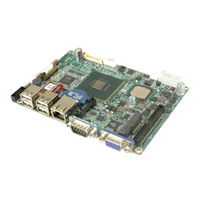
Intel Atom based 3,5"" CPU Module, Up to 2.0 GB DDR2, VGA, LVDS, Mini PCIe, RS-232/422/485, IDE, CompactFlash, 6 x USB, RoHS
Brand:
IEI Technology
| Category:
Motherboard
| Size: 2.6 MB
Table of Contents
Table of Contents
4
User Manual
1
1 Introduction
11
Introduction
12
Benefits
12
Features
13
Connectors
13
Dimensions
14
Figure 1-2: Connectors
14
Figure 1-3: WAFER-US15WP Dimensions (MM)
15
Data Flow
16
Figure 1-4: Data Flow Diagram
16
Technical Specifications
17
Table 1-1: Technical Specifications
18
2 Packing List
19
Anti-Static Precautions
20
Unpacking Precautions
20
Packing List
21
Optional Items
22
Table 2-1: Packing List
22
Table 2-2: Optional Items
22
3 Connector Pinouts
23
Peripheral Interface Connectors
24
Figure 3-1: Connector and Jumper Locations
24
Layout
24
External Interface Panel Connectors
25
Peripheral Interface Connectors
25
Table 3-1: Peripheral Interface Connectors
25
Internal Peripheral Connectors
26
ATX Power Connector
26
Figure 3-2: ATX Power Connector Location
26
Table 3-2: Rear Panel Connectors
26
ATX Standby Power Connector
27
Figure 3-3: ATX Standby Power Connector Location
27
Table 3-3: ATX Power Connector Pinouts
27
Table 3-4: ATX Standby Power Connector Pinouts
27
Audio Connector
28
Backlight Inverter Connector
28
Figure 3-4: Audio Connector Locations
28
Table 3-5: Audio Connector Pinouts
28
Battery Connector
29
Figure 3-5: Backlight Inverter Connector
29
Table 3-6: Backlight Inverter Connector
29
Compactflash® Slot
30
Figure 3-6: Battery Connector Location
30
Figure 3-7: Compactflash® Slot Location
30
Table 3-7: Battery Connector Pinouts
30
Digital I/O Connector
31
Fan Connector
31
Figure 1-1: WAFER-US15WP
31
Figure 3-8: Digital I/O Connector Locations
31
Table 3-8: Digital I/O Connector Pinouts
31
Figure 3-9: Fan Connector Location
32
Front Panel Connector
32
Table 3-9: Fan Connector Pinouts
32
Figure 3-10: Front Panel Connector Location
33
IDE Connector
33
Table 3-10: Front Panel Connector Pinouts
33
Figure 3-11: IDE Connector Locations
34
Figure 3-12: Keyboard/Mouse Connector Location
34
Keyboard/Mouse Connector
34
Table 3-11: Keyboard/Mouse Connector Pinouts
34
Figure 3-13: LVDS Connector Location
35
LVDS Connector
35
Figure 3-14: LPC Connector Location
36
LPC Interface Connector
36
Pcie Mini Card Slot
36
Table 3-12: LVDS Connector Pinouts
36
Table 3-13: LPC Connector Pinouts
36
Figure 3-15: Pcie Mini Card Slot Location
37
Figure 3-16: Serial Port Connector Locations
37
Serial Port Connectors
37
Figure 3-17: USB Connector Location
38
Table 3-14: Serial Port Connector Pinouts
38
USB Connector
38
External Interface Connectors
39
Ethernet Connector
39
Figure 3-18: External Interface Connectors
39
Table 3-15: USB Port Connector Pinouts
39
Table 3-16: Ethernet Connector Pinouts
39
Figure 3-19: Ethernet Connector
40
Serial Port Connector
40
Table 3-17: Connector Leds
40
Table 3-18: Serial Port Pinouts
40
Figure 3-20: Serial Port Pinout Locations
41
Table 3-19: USB Connector Pinouts
41
USB Ports
41
VGA Connector
41
Figure 3-21: VGA Connector
42
Table 3-20: VGA Connector Pinouts
42
4 Installation
43
Anti-Static Precautions
44
Installation Considerations
44
Jumper Settings
46
Table 4-1: Jumpers
46
Clear CMOS Jumper
47
Figure 4-1: Jumpers
47
AT/ATX Mode Selection
48
LVDS Voltage Selection
48
Table 4-2: Clear CMOS Jumper Settings
48
Table 4-3: AT/ATX Mode Selection
48
COM2 RS-232/422/485 Selection
49
Compactflash® Master/Slave Selection
49
Table 4-4: LVDS Voltage Selection
49
Table 4-5: Compactflash® Master/Slave Selection
49
Table 4-6: COM2 RS-232/422/485 Selection
49
5 Bios
50
Introduction
51
Starting Setup
51
Using Setup
51
BIOS Menu Bar
52
Getting Help
52
Table 5-1: BIOS Navigation Keys
52
Unable to Reboot after Configuration Changes
52
Main
53
BIOS Menu 1: Main
53
System Overview
53
Advanced
54
BIOS Menu 2: Advanced
54
System Date [XX/XX/XX]
54
System Time [XX:XX:XX]
54
CPU Configuration
55
BIOS Menu 3: CPU Configuration
55
IDE Configuration
56
BIOS Menu 4: IDE Configuration
56
IDE Master and IDE Slave
56
Onboard PCI IDE Controller [Primary]
56
IDE Master, IDE Slave
57
BIOS Menu 5: IDE Master and IDE Slave Configuration
57
Auto-Detected Drive Parameters
57
Lba/Large Mode [Auto]
58
Type [Auto]
58
Block (Multi Sector Transfer) [Auto]
59
PIO Mode [Auto]
59
Auto]
60
DMA Mode [Auto]
60
Super IO Configuration
61
BIOS Menu 6: Super IO Configuration
61
32Bit Data Transfer [Enabled]
61
Serial Port1 Address [3F8]
61
Hardware Health Configuration
62
BIOS Menu 7: Hardware Health Configuration
62
Mode Setting [Full on Mode]
62
Serial Port2 Address [2F8]
62
CPU Temperature Limit of off [000]
63
CPU Temperature Limit of Start [020]
63
Fan Start PWM [070]
64
Slope PWM [0.5 PWM]
64
Remote Access Configuration
65
BIOS Menu 8: Remote Access Configuration
65
Remote Access [Disabled]
65
Base Address, IRQ [3F8H,4]
66
Redirection after BIOS POST [Always]
66
Serial Port Mode [115200 8,N,1]
66
Serial Port Number [COM1]
66
USB Configuration
67
BIOS Menu 9: USB Configuration
67
Terminal Type [ANSI]
67
USB Function [Enabled]
67
Legacy USB Support [Enabled]
68
USB 2.0 Controller [Enabled]
68
USB2.0 Controller Mode [Hispeed]
68
USB Mass Storage Device Configuration
69
BIOS Menu 10: USB Mass Storage Device Configuration
69
Device
69
USB Mass Storage Reset Delay [20 Sec]
69
Emulation Type [Auto]
70
Pci/Pnp
71
BIOS Menu 11: Pci/Pnp Configuration
71
IRQ# [Available]
71
Reserved Memory Size [Disabled]
71
Boot
72
BIOS Menu 12: Boot
72
Boot Settings Configuration
73
BIOS Menu 13: Boot Settings Configuration
73
Quick Boot [Enabled]
73
Quiet Boot [Disabled]
73
Addon ROM Display Mode [Force BIOS]
74
Boot from LAN Support [Disabled]
74
Bootup Num-Lock [On]
74
Boot Device Priority
75
BIOS Menu 14: Boot Device Priority Settings
75
Hard Disk Drives
76
Removable Drives
76
BIOS Menu 15: Hard Disk Drives
76
BIOS Menu 16: Removable Drives
76
CD/DVD Drives
77
Security
77
BIOS Menu 17: CD/DVD Drives
77
BIOS Menu 18: Security
77
Chipset
78
BIOS Menu 19: Chipset
78
Change Supervisor Password
78
Change User Password
78
Northbridge Configuration
79
BIOS Menu 20:Northbridge Chipset Configuration
79
Integrated Graphics Mode Select [Enable, 4 MB]
79
Primary Graphics Adapter [Pcie/Igd]
79
Boot Display Device
80
Flat Panel Type
80
Southbridge Configuration
81
BIOS Menu 21:Southbridge Chipset Configuration
81
Audio Controller Codec [Auto]
81
Exit
82
BIOS Menu 22:Exit
82
Discard Changes
82
Discard Changes and Exit
82
Load Optimal Defaults
82
Save Changes and Exit
82
Load Failsafe Defaults
83
ABIOS Options
84
Appendix A
85
B Terminology
87
C Hazardous Materials Disclosure
91
Hazardous Materials Disclosure Table for IPB Products Certified as Rohs Compliant under 2002/95/EC Without Mercury
92
C.1 H Azardous M Aterials D Isclosure T Able for Ipb P Roducts C Ertified as R O Hs C Ompliant U Nder 2002/95/Ec W Ithout M Ercury
92
Advertisement
Advertisement
Related Products
IEI Technology WAFER-US15WP2
IEI Technology WAFER-LX
IEI Technology WAFER-PV-D4252
IEI Technology WAFER-945GSELVDS2
IEI Technology WAFER-945GSE2
IEI Technology WAFER-PV-D4253
IEI Technology WAFER-PV-D5253
IEI Technology WAFER-4823
IEI Technology WAFER-BW-N2-R10
IEI Technology WAFER-LX-800-R10
IEI Technology Categories
Motherboard
Touch Panel
Computer Hardware
Single board computers
Desktop
More IEI Technology Manuals
Login
Sign In
OR
Sign in with Facebook
Sign in with Google
Upload manual
Upload from disk
Upload from URL