Sign In
Upload
Manuals
Brands
IAI Manuals
Controller
SCON-CB-F
IAI SCON-CB-F Manuals
Manuals and User Guides for IAI SCON-CB-F. We have
3
IAI SCON-CB-F manuals available for free PDF download: Instruction Manual
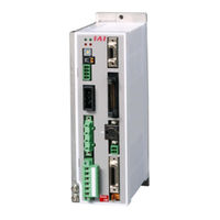
IAI SCON-CB-F Instruction Manual (450 pages)
SCON-CB Series, PLC Feature Equipped / Safety Category Complied / Safety Categories Complying PLC Feature Equipped Type
Brand:
IAI
| Category:
Controller
| Size: 20 MB
Table of Contents
Table of Contents
7
Safety Guide
17
Precautions in Operation
24
International Standards Compliances
28
Name for each Parts and Their Functions
29
About SCON-LC Type (Only for Types up to 750W)
35
Actuator Axes
37
Chapter 1 Specifications Check
39
Product Check
39
Parts
39
Teaching Tool
41
Lnstruction Manuals Related to this Product, Which Are Contained in the Instruction
41
Manual (DVD)
41
How to Read the Model Plate
42
How to Read the Model of the Controller
42
Basic Specifications
43
Specifications
43
Power Capacity and Heat Generation
45
Selection of Circuit Interrupter
45
Selection of Leak Current Breaker
46
Appearance
47
SCON-CB/CGB/LC/LCG Less than 400W
47
SCON-CB/CGB/LC/LCG 400W to 750W
47
SCON-CGB 3000W and above
48
I/O Specifications
49
PIO Input and Output Interface
49
Pulse Train Input Output Interface (Excluding Type for 3000W and Above, LC Type and Feeldbus Type)
50
Options
50
Pulse Conveter : AK-04
50
Pulse Conveter : JM-08
51
Regenerative Unit (Option)
52
Brake Box : RCB-110-RA13-0
54
Loadcell (Excluding RCS3-RA15R and RCS3-RA20R)
55
Installation and Storage Environment
56
Noise Elimination and Mounting Method
57
Chapter 2 Wiring
61
Positioner Mode (PIO Control) (Controller for Motors of up to 750W)
61
Wiring Diagram (Connection of Construction Devices)
61
PIO Pattern Selection and PIO Signal
63
Wiring
68
Positioner Mode (PIO Control) (Controller for Motors of 3000W and Above)
85
Wiring Diagram (Connection of Devices)
85
PIO Pattern Selection and PIO Signal
86
Wiring
91
Pulse Train Control Mode (Only for Controller for Motors of up to 750W)
104
Wiring Diagram (Connection of Construction Devices)
104
I/O Signals in Pulse Train Control Mode
106
Wiring
108
SCON-LC/LCG Type
116
Wiring Diagram (Connection of Construction Devices)
116
I/O Signals in LC Type
118
Wiring
119
Wiring Method (Controller for Motors of up to 750W)
127
Wiring of Power Circuit
127
Wiring for Emergency Stop Circuit (System I/O)
132
Connection to Actuator
134
Connection of PIO
136
Pulse Train Signal Input and Feedback Pulse Output (CB/CGB Type)
137
Multi-Function Connector (LC/LCG Type)
140
Connectable Regenerative Units
143
SIO Connecter Connection
145
Wiring (Controller for Motors of 3000W and Above)
146
Wiring for Power Supply Circuit
146
Wiring of Emergency Stop Circuit (System I/O)
150
Connection to Actuator
152
Connection of PIO
154
Multi-Function Connector
155
Connection of Regenerative Unit
158
SIO Connector Connection
160
Chapter 3 Operation
161
Basic Operation
161
Power Supply and Cutoff
161
Basic Operation Methods
162
Parameter Settings
165
Operation in Positioner Mode
166
Set of Position Table
169
(This Section Is Not Required in Selection of Pulse Train Control Mode.)
169
Control of Input Signal
176
Operation Ready and Auxiliary Signals = Common to Patterns 0 to 7
176
Operation with the Position No. Input = Operations of PIO Patterns 0 to 3 and 6
188
Direct Position Specification (Solenoid Value Mode 1) = Operations of
212
PIO Patterns 4 or 7
212
PIO Pattern 4 or
212
Direct Position Specification (Solenoid Value Mode 2) = Operations of
229
PIO Patterns 5
229
Operation Ready for Pressing Operation Using Force Sensor
238
(Calibration of Loadcell)
238
Operation in Pulse Train Control Mode (Only for Types up to 750W)
242
I/O Signal Controls
243
Operation Ready and Auxiliary Signals
244
Pulse Train Input Operation
253
Setting of Basic Parameters Required for Operation
257
Output Setting of Feeldback Pulse
260
Parameter Settings Required for Advanced Operations
264
Chapter 4 Field Network
267
Each Field Network
267
RCON Connection Type
271
Model Codes for RCON Connection Type
271
Connection to RCON
271
Specifications
272
Name for each Parts and Their Functions
272
Pin Assignment on Connector
273
LED Display
274
Related Parts
274
Timing to Supply Power
275
Chapter 5 Vibration Suppress Control Function
277
Setting Procedure
279
Settings of Parameters for Vibration Suppress Control
280
Setting of Position Data
281
Chapter 6 Power-Saving Function (Auto Servo-Motor off Function)
283
Chapter 7 Absolute Reset and Absolute Battery
285
Absolute Reset
285
Absolute Battery
290
Absolute Encoder Backup Specifications
290
Replacement of Absolute Battery
292
Chapter 8 Parameter
293
Parameter List
294
Detail Explanation of Parameters
299
Servo Adjustment
338
Chapter 9 Troubleshooting
341
Action to be Taken Upon Occurrence of Problem
341
Fault Diagnosis
342
Impossible Operation of Controller
342
Positioning and Speed of Poor Precision (Incorrect Operation)
345
Generation of Noise And/Or Vibration
347
Impossible Communication
348
Alarm Level
349
Alarm List
350
Chapter 10 Appendix
363
Way to Set Multiple Controllers with 1 Teaching Tool
363
Connecting Example
363
Detailed Connection Diagram of Communication Lines
364
Axis No.setting
365
Handling of E-CON Connector (How to Connect)
366
SIO Converter
367
Communications Cable
369
External Dimension
369
Conformity to Safety Category
370
Maintenance
382
Consumed Parts
382
Maintenance Information
382
Example of Basic Positioning Sequence (PIO Pattern 0 to 3)
383
I/O Assignment
383
Ladder Sequence
384
List of Specifications of Connectable Actuators
395
List of Specifications for Actuator Operation Conditions
395
Specifications and Limitations in Pressing Operation
440
Warranty
445
Warranty Period
445
Scope of the Warranty
445
Honoring the Warranty
445
Limited Liability
445
Chapter 11 Warranty
445
Conditions of Conformance with Applicable Standards/Regulations, Etc., and Applications
446
Other Items Excluded from Warranty
446
Change History
447
Advertisement
IAI SCON-CB-F Instruction Manual (376 pages)
Servo Press Function
Brand:
IAI
| Category:
Controller
| Size: 17 MB
Table of Contents
Please Read before Use
3
Table of Contents
5
Operation Description
11
Safety Guide ꞏꞏꞏꞏꞏꞏꞏꞏꞏꞏꞏꞏꞏꞏꞏꞏꞏꞏꞏꞏꞏꞏꞏꞏꞏꞏꞏꞏꞏꞏꞏꞏꞏꞏꞏꞏꞏꞏꞏꞏꞏꞏꞏꞏꞏꞏꞏꞏꞏꞏꞏꞏꞏꞏꞏꞏꞏꞏꞏꞏꞏꞏꞏꞏꞏꞏꞏꞏꞏꞏꞏꞏꞏꞏꞏꞏꞏꞏꞏꞏꞏꞏ Intro-1
11
Alert Indication
17
Precautions for Handling ꞏꞏꞏꞏꞏꞏꞏꞏꞏꞏꞏꞏꞏꞏꞏꞏꞏꞏꞏꞏꞏꞏꞏꞏꞏꞏꞏꞏꞏꞏꞏꞏꞏꞏꞏꞏꞏꞏꞏꞏꞏꞏꞏꞏꞏꞏꞏꞏꞏꞏꞏꞏꞏꞏꞏꞏꞏꞏꞏꞏꞏꞏꞏꞏꞏꞏꞏ Intro-9
19
International Standard Compliance ꞏꞏꞏꞏꞏꞏꞏꞏꞏꞏꞏꞏꞏꞏꞏꞏꞏꞏꞏꞏꞏꞏꞏꞏꞏꞏꞏꞏꞏꞏꞏꞏꞏꞏꞏꞏꞏꞏꞏꞏꞏꞏꞏꞏꞏꞏꞏꞏꞏꞏꞏꞏꞏꞏ Intro-13
23
Actuator Coordinate System ꞏꞏꞏꞏꞏꞏꞏꞏꞏꞏꞏꞏꞏꞏꞏꞏꞏꞏꞏꞏꞏꞏꞏꞏꞏꞏꞏꞏꞏꞏꞏꞏꞏꞏꞏꞏꞏꞏꞏꞏꞏꞏꞏꞏꞏꞏꞏꞏꞏꞏꞏꞏꞏꞏꞏꞏꞏꞏꞏꞏꞏꞏ Intro-14
24
Chapter 1 Controller Overview
25
Overview
27
System Configuration
28
Name for each Parts and Their Functions
30
Starting Procedures
39
Step 1 Confirm All the Necessary Things Are Prepared
39
Step 2 Installation
40
Step 3 Wiring
42
Step 4 Operation Ready
43
Step 5 Operate Unit
44
Specifications Check
45
Product Check
47
Parts
47
Teaching Tool
49
Product Check
49
How to Read the Model Plate
50
How to Read the Model
51
Basic Specifications
53
List of Basic Specifications
53
Power Capacity and Heat Generation
55
Selection of Circuit Interrupter
56
Selection of Leak Current Breaker
56
Appearance
57
SCON-CB/CGB/LC/LCG Less than 400W
57
SCON-CB/CGB/LC/LCG 400W to 750W
57
SCON-CGB 3000W and above
58
External Interface Specifications
59
Standard Input Output Interface Specification (Multi-Function Connector)
59
Standard Input Output Interface Specification
59
PIO Input and Output Interface
61
Input Section
61
Output Section
61
Options
62
Pulse Converter (Model: JM-08)
62
Regenerative Resistor Unit
63
Brake Box: RCB-110-RA13-0
65
Loadcell
66
Absolute Battery
67
Absolute Encoder Backup Specifications
67
Installation and Storage Environment
69
Installation Environment
69
Storage and Preservation Environment
69
Noise Elimination and Mounting Method
70
Noise Elimination
70
Installation and Mounting
71
Servo Press Controller for Motors of up to 750W (PIO Control)
73
Wiring Diagram (Connection of Construction Devices)
75
Wiring
77
Main Power Circuit
77
Brake Power Supply Circuit
77
Actuator Type
81
PIO Circuit
85
Servo Press Controller for Motors of 3000W and above (PIO Control)
90
Wiring Diagram (Connection of Construction Devices)
90
Wiring
91
System I/O Connector
92
PIO Circuit
98
Wiring Method (Controller for Motors of up to 750W)
103
Wiring of Power Circuit
103
Wiring of Emergency Stop Circuit (System I/O)
108
Connection to Actuator
110
Connection of PIO
112
Multi-Function Connector
113
Connectable Regenerative Resistor Units
118
SIO Connecter Connection
121
Wiring (Controller for Motors of 3000W and Above)
122
Wiring for Power Supply Circuit
122
Wiring of Emergency Stop Circuit (System I/O)
126
Connection to Actuator
128
Connection of PIO
130
Multi-Function Connector
131
Connectable Regenerative Resistor Units
135
SIO Connector Connection
138
Field Network Connector of PIO
139
Operation
141
Basic Operation
143
How to Turn on Power
143
Operation Mode
144
Basic Operation Setting
153
Detailed Settings
162
Trial Operation
169
Manual Operation (Jog Etc)
170
Press Program Operation
171
Operation with PIO
173
Control of Input Signal
173
Operation Ready and Auxiliary Signals
173
Home Return (HOME, HEND)
176
Operation
181
Example of Operation
185
Operation of Field Network Type
187
Operation in Pressing Direct Mode
188
Pressing Direct Mode
188
Applicable Models and Operation Mode
189
Signal Assignment and Input/Output Signals
190
I/O Signal Allocation
191
Absolute Reset
211
How to Perform Absolute Reset
212
Absolute Reset Using PIO
217
Various Functions
219
Feature of Multi-Function Connector
221
Overview
221
How to Set up
222
Analog Output of Load Data
226
Specification
226
Setting
227
Rated Capacity of Loadcell Mounted to each Actuator
227
Serial Communication 2 (SIO2)
228
Specification
228
Setting
229
Parameter List
234
Input Range
248
Default Factory Setting
248
Servo Adjustment
271
Adjustment Method
272
Maintenance and Inspection
273
Periodic Inspection
275
Periodic Inspection Items
276
Requests When Replacing Units
278
Consumable Parts
279
Component Replacement
280
Replacement of Absolute Battery
280
Fan Unit Replacing Procedure (SCON-CB 3000W and Above)
281
Preventive Maintenance Function
284
Maintenance Information
284
Predictive Maintenance Function
288
Fan
288
Overload Warning
289
Troubleshooting
291
Action to be Taken Upon Occurrence of Problem
293
Fault Diagnosis
295
Impossible Operation of Controller
295
Generation of Noise And/Or Vibration
296
About Alarms
297
Alarm Level
297
Alarm Details
298
System Configuration
319
Wiring and Setting of Safety Circuit
320
Examples of Safety Circuits
322
TP Adapter and Related Components
328
Connection Cable
329
Applicable Standards
331
Residual Risk
332
Specifications
335
Operating Sequence
336
Electric Specifications
339
Maintenance and Preservation
342
Way to Set Multiple Controllers with 1 Teaching Tool
345
Connecting Example
346
Detailed Connection Diagram of Communication Lines
347
Axis No. Setting
348
Handling of E-CON Connector (How to Connect)
349
SIO Converter
350
Communications Cable
352
External Dimension
352
Example of Basic Positioning Sequence (PIO Pattern 0 to 3)
353
I/O Assignment
353
Ladder Sequence
354
Pause Circuit
355
Home Return Circuit
356
Decode Circuit of Positioning Complete Position no
357
Actuator Start Circuit
357
Other Display Circuits (Zone 1, Position Zone, and Manual Mode)
363
Warranty
369
Limited Liability
372
Conformance with Applicable Standards/Regulations, Etc., and Application Conditions
372
Revision Date
374
IAI SCON-CB-F Instruction Manual (244 pages)
SCON-CB Series
Brand:
IAI
| Category:
Controller
| Size: 12 MB
Table of Contents
Table of Contents
7
Safety Guide
17
Precautions in Operation
24
International Standards Compliances
27
Name for each Parts and Their Functions
28
About SCON-LC Type
34
Actuator Axes
36
Chapter 1 Specifications Check
37
Product Check
37
Parts
37
Teaching Tool
39
Instruction Manuals Related to this Product, Which Are Contained in the Instruction
39
Manual (DVD)
39
How to Read the Model Plate
39
How to Read the Model
40
List of Basic Specifications
41
Specification List
41
Item for the Power Capacity and Heating Value
43
Selection of Circuit Breaker
43
Selection of Leakage Breaker
43
External Dimensions
44
SCON-CB/CGB/LC/LCG Less than 400W
44
SCON-CB/CGB/LC/LCG 400W to 750W
44
SCON-CB/CGB/LC/LCG 3000W to 3300W
45
External Interface Specifications
46
Standard Input Output Interface Specification (Multi-Function Connector)
46
Input Output Interface Specification Dedicated for PIO Type
47
Filedbus Type Specifications
48
Options
51
Regenerative Unit for Motors of up to 750W
51
Regenerative Unit for Motors of 3000W and above
52
Brake Box: RCB-110-RA13-0
53
Load Cell
54
Pulse Converter: JM-08
55
Installation and Storage Environment
56
Noise Elimination and Mounting Method
57
Chapter 2 Wiring
61
Servo Press Controller for Motors of up to 750W (PIO Control)
61
Wiring Diagram (Connection of Devices)
61
Wiring
62
Wiring for Controller for Motors of up to 750W
75
Wiring for Power Supply Circuit
75
Wiring of Emergency Stop Circuit (System I/O)
80
Connection of Actuator
82
Connection of PIO
84
Multi-Function Connector
85
Connection of Regenerative Unit
88
SIO Connector Connection
90
Servo Press Controller for Motors of 3000W and above (PIO Control)
91
Wiring Diagram (Connection of Devices)
91
Wiring
92
Controller for Motors of 3000W and above
104
Wiring for Power Supply Circuit
104
Wiring of Emergency Stop Circuit (System I/O)
108
Connection of Actuator
110
Connection of PIO
112
Multi-Function Connector
113
Connection of Regenerative Unit
116
SIO Connector Connection
118
Chapter 3 Operation
119
Explain the Operation Mode and Setting
119
Power Supply and Cutoff
119
Explain the Operation Mode
120
Basic Operation Setting
126
Detailed Settings (Optional Settings)
133
Trial Run
138
Manual Operation (Jog Etc)
138
Press Program Operation
139
Operation with PIO
141
I/O Signal Controls
141
Operation Ready and Auxiliary Signals
141
Operation
146
Chapter 4 Applicability to Fieldbus
151
Chapter 5 Feature of Multi-Function Connector
155
Feedback Pulse Output
155
Setting
155
Analog Output of Load Data
158
Specification
158
Setting
158
Rated Capacity of Loadcell Mounted to each Actuator
158
Serial Communication 2 (SIO2)
159
Specification
159
Setting
159
Chapter 6 Absolute Type
160
Absolute Reset
160
Absolute Battery
161
Absolute Encoder Backup Specifications
161
Replacement of Absolute Battery
162
Chapter 7 Parameter
163
Parameter List
164
Detail Explanation of Parameters
167
Servo Adjustment
194
Chapter 8 Troubleshooting
196
Action Taken Upon Occurence of Problem
196
Fault Diagnosis
197
Impossible Operation of Controller
197
Generation of Noise And/Or Vibration
197
Alarm Level
198
Alarm List
199
Controller Alarm (Excluding Program Alarm)
199
Program Alarm (When Controller Alarm 094 Is Issued)
209
Chapter 9 Appendix
215
Way to Set Multiple Controllers with 1 Teaching Tool
215
Connecting Example
215
Detailed Connection Diagram of Communication Lines
216
Axis No. Setting
217
Handling of E-CON Connector (How to Connect)
218
SIO Converter
219
Communications
221
External Dimension
221
Conformity to Safety Category of to 750W Motor Corresponding SCON
222
Maintenance
233
List of Specifications of Connectable Actuators
234
List of Specifications for Actuator Operation Conditions
234
Specifications and Limitations in Pressing Operation
234
Chapter 10 Warranty
239
Warranty Period
239
Scope of the Warranty
239
Honoring the Warranty
239
Limited Liability
239
Conditions of Conformance with Applicable Standards/Regulations, Etc
240
And Applications
240
Other Items Excluded from Warranty
240
Change History
241
Advertisement
Advertisement
Related Products
IAI SCON-CA
IAI SCON-CAL
IAI SCON-CGAL
IAI SCON-CGB-F
IAI SCON-CGB
IAI SCON-CB
IAI SCON-CB Series
IAI scon
IAI SCON-LCG-F
IAI SCON2
IAI Categories
Controller
Digital Camera
Gateway
Industrial Equipment
Security Camera
More IAI Manuals
Login
Sign In
OR
Sign in with Facebook
Sign in with Google
Upload manual
Upload from disk
Upload from URL