Sign In
Upload
Manuals
Brands
Hypertherm Manuals
Cutter
HyPerformance Plasma HPR800XD
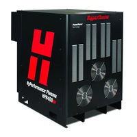
Hypertherm HyPerformance Plasma HPR800XD Manuals
Manuals and User Guides for Hypertherm HyPerformance Plasma HPR800XD. We have
4
Hypertherm HyPerformance Plasma HPR800XD manuals available for free PDF download: Instruction Manual, Manual, Field Service Bulletin
Hypertherm HyPerformance Plasma HPR800XD Instruction Manual (366 pages)
Auto Gas, Plasma Cutting System
Brand:
Hypertherm
| Category:
Cutter
| Size: 48.33 MB
Table of Contents
Table of Contents
9
Electromagnetic Compatibility (Emc)
5
Warranty
7
Table of Contents
9
Table of Contents
15
Safety
18
Recognize Safety Information
18
Follow Safety Instructions
18
Inspect Equipment before Using
18
Responsibility for Safety
18
A Plasma Arc Can Damage Frozen Pipes
18
Static Electricity Can Damage Printed Circuit Boards
18
Grounding Safety
19
Electrical Hazards
19
Electric Shock Can Kill
19
Cutting Can Cause Fire or Explosion
20
Machine Motion Can Cause Injury
20
Compressed Gas Equipment Safety
21
Gas Cylinders Can Explode if Damaged
21
Toxic Fumes Can Cause Injury or Death
21
A Plasma Arc Can Cause Injury and Burns
22
Arc Rays Can Burn Eyes and Skin
22
Pacemaker and Hearing Aid Operation
22
Noise Can Damage Hearing
23
Dry Dust Collection Information
23
Laser Radiation
24
Additional Safety Information
24
Section 2 Specifications
25
Specifications
25
System Description
27
Chiller
27
Chiller Interface Console
27
General
27
Ignition Console
27
Metering Console
27
Power Supplies
27
Selection Console
27
Torch
27
Specifications
28
System Gas Requirements
28
General
29
Power Supplies
29
Chiller
30
Chiller Interface Console - 078537
31
Ignition Console - 078536
32
Torch Lead Junction Box (Optional) - 078619
34
Selection Console - 078533
35
Metering Console - 078535
36
Torch - 228599
37
IEC Symbols
38
Symbols and Marks
39
Section 3 Installation
41
Installation
41
Section 3 Installation
41
Upon Receipt
43
Claims
43
Installation Requirements
43
Noise Levels
43
Placement of System Components
43
Installation Requirements
44
Cables and Hoses
45
Customer-Supplied Power Cables
45
Supply Gas Hoses
45
System Components
45
Recommended Grounding and Shielding Practices
46
Introduction
46
Grounding Practices
46
Types of Grounding
46
Grounding Diagram
49
Placement of the Primary Power Supply
51
Placement of the Secondary Power Supply
52
Lifting the Power Supply
53
Install the Ignition Console
55
Placement of the Chiller
57
Install the Chiller Interface Console
58
Install the Metering Console
59
Placement of the Selection Console
60
Primary Power Supply to Secondary Power Supply Cables
61
Interface (On/Off) Cable
61
Communication Cable
62
Power Supply to Ignition Console Leads
63
Negative Leads
63
Pilot Arc Lead
63
Coolant Hose Set (Chiller to Chiller-Interface Console)
66
Coolant Hose Set (Chiller-Interface Console to Ignition Console)
67
Primary Power Supply to Chiller Interface Console
68
Chiller Interface Power Cable
68
Secondary Power Supply to Chiller Interface Console
69
Chiller Interface Communication Cable
69
Primary Power Supply to Selection Console Cables
70
Selection Console Communication Cable
70
Selection Console Power Cable
70
Selection Console to Metering Console Hose and Lead Assembly
72
Cable and Gas Hose Assembly
72
Power Supply to CNC Interface Cable
74
Optional Multi-System CNC Interface Cable
74
Examples of Output Circuits
76
Examples of Input Circuits
77
Remote ON/OFF Switch (Provided by Customer)
78
Torch Lead Assembly
79
Torch Lead Junction Box (Optional)
80
Install the Junction Box
81
Connect the Leads
82
Work Lead
86
Torch Connections
87
Connect the Torch to the Torch Lead Assembly
87
Connect the Torch to the Quick-Disconnect
91
Torch Mounting and Alignment
92
Mounting the Torch
92
Torch Alignment
92
Torch Lifter Requirement
93
Hypernet
93
General
94
Line Disconnect Switch
95
Main Power Cable (Power Supplies)
95
Main Power Cable (Chiller)
95
Connect the Power
96
Torch Coolant Requirements
97
Premixed Coolant for Standard Operating Temperatures
97
Custom Coolant MIX for Cold Operating Temperatures
98
Custom Coolant MIX for Hot Operating Temperatures
99
Water Purity Requirements
99
Fill the Chiller with Coolant
100
Gas Requirements
101
Setting the Supply Regulators
101
Gas Regulators
102
Supply Gas Plumbing
103
Connect the Supply Gases
104
Supply Gas Hoses
105
Section 4 Operation
107
Operation
107
Daily Start-Up
109
Check Torch
109
Power Indicators
110
Chiller Interface Console
110
General
110
Metering Console
110
Power Supply
110
Selection Console
110
CNC Controller Requirements
111
CNC Screen Examples
112
Main (Control) Screen
112
Diagnostic Screen
113
Test Screen
114
Cut Chart Screen
115
Consumable Selection
116
Bevel Cutting (0° to 45°)
116
Consumables for Mirror-Image Cutting
116
Marking
116
Powerpierce Technology
116
Silverplus Electrodes
116
Standard Cutting (0°)
116
Mild Steel
117
Stainless Steel
118
Aluminum
119
Mild Steel Bevel Cutting
120
Mild Steel, Thick Piercing, Bevel Cutting
120
Stainless Steel Bevel Cutting
121
Install and Inspect Consumables
122
Torch Maintenance
125
Maintenance Kit
125
Quick-Disconnect Maintenance
125
Routine Maintenance
125
Torch Connections
126
Replace Torch Water Tube
126
Common Cutting Faults
127
How to Optimize Cut Quality
128
Maximize the Life of Consumable Parts
128
Plasma Set-Up Tips
128
Tips for Table and Torch
128
Additional Factors of Cut Quality
129
Additional Improvements
131
Cut Charts
132
Thin Stainless Steel with Hdi Technology
132
Overview
132
Thick Stainless Steel Piercing Technique
133
Overview
133
Fine Feature Cutting
135
Overview
135
Recommendations
135
Bevel Cutting
136
Bevel Compensation Tables
136
Consumables
136
Bevel Cutting Definitions
137
Cutting Thick Material
138
Overview
139
Underwater Cut Charts
139
Estimated Kerf-Width Compensation
141
Section 5 Maintenance
215
Introduction
217
Routine Maintenance
217
System Description
218
Power and Signal Cables
218
Sequence of Operation
219
Gas System Purge Cycle
220
Gas System Valve Usage
220
Marking Process
222
Power Supply Troubleshooting
223
Error Codes
224
Error Code Troubleshooting - Error Codes 000 to 018
225
Error Code Troubleshooting - Error Codes 020 to 028, 224 to 228
226
Error Code Troubleshooting - Error Codes 030 to 042, 231 to 234
227
Error Code Troubleshooting - Error Codes 044 to 046
228
Error Code Troubleshooting - Error Codes 047 to 053, 248 to 250
229
Error Code Troubleshooting - Error Codes 054 to 061
230
Error Code Troubleshooting - Error Codes 062 to 067, 265 to 267
231
Error Code Troubleshooting - Error Codes 071 to 075, 273 to 275
232
Error Code Troubleshooting - Error Codes 076 to 101, 276 to 301
233
Error Code Troubleshooting - Error Codes 102 to 111, 302 to 308
234
Error Code Troubleshooting - Error Codes 116 to 133, 316
235
Error Code Troubleshooting - Error Codes 134 to 140, 334 and 338
236
Error Code Troubleshooting - Error Codes 141 to 152, 346 to 351
237
Error Code Troubleshooting - Error Codes 153 to 156, 354 to 356
238
Error Code Troubleshooting - Error Codes 157 to 159, 357 to 359
239
Error Code Troubleshooting - Error Codes 160 to 180
240
Error Code Troubleshooting - Error Code 181, 182, 298, and 383
241
Power Supply States
242
Plasma System Operation with Pump Time-Out
243
CNC Operation with Pump Time-Out
244
Initial Checks
245
Power Measurement
246
Air Filter Element Replacement
247
Coolant System Servicing
248
Draining the Coolant System
248
Chiller Interface Coolant Filter
250
Filter Replacement
250
Gas Leak Tests
251
Leak Test 1 (Inlet Leak Test)
251
Leak Test 2 (System Leak Test)
252
Leak Test 3 (Proportional Valve Test in the Metering Console)
252
Power Supply Control Board PCB3
253
Power Supply Power Distribution Board PCB2
254
Start-Circuit PCB1
255
Operation
255
Start Circuit Functional Schematic
255
Start Circuit Troubleshooting
255
Pilot Arc Current Levels
257
Pump Motor Drive Board PCB7
258
Chiller Interface Power Distribution Board PCB1
259
Coolant Sensor Board PCB2
260
Selection Console Control Board PCB2
261
Selection Console Power Distribution Board PCB1
262
Selection Console, AC Valve-Driver Board PCB3
263
Metering Console Control Board PCB2
264
Metering Console Power Distribution Board PCB1
265
Chopper Tests
266
Phase-Loss Detection Test
268
Torch Lead Test
269
Preventive Maintenance
270
Section 6 Parts List
271
Parts List
271
Power Supply
272
Chiller
276
Chiller Interface Console
277
Ignition Console
278
Torch Lead Junction Box (Optional)
279
Ignition Console to Junction Box Leads
280
Metering Console
283
Hyperformance Torch
284
Torch Assembly
284
Ohmic Contact Wire
285
Torch Leads
285
Consumable Parts Kits
286
Consumable Parts Kits
288
Consumables for Mirror-Image Cutting
289
Straight Cutting
289
Bevel Cutting
291
Recommended Spare Parts
293
Warning Label - 110647
296
Wiring Diagrams
297
Discrete Output Functionality
300
Appendix A Hypertherm Torch Coolant Safety Data
325
Identification of the Substance/Mixture and of the Company Undertaking
326
Composition/Information on Ingredients
327
Handling and Storage
328
Stability and Reactivity
329
Disposal Considerations
330
Other Information
331
Freezing Point of Propylene Glycol Solution
332
Checksum
333
Appendix B Interface Hardware
334
Hardware
335
Multi-Drop Wiring
336
Multi-Drop Addressing
337
Command Table (1 of 14)
338
Error Responses
352
Error Codes
353
Status Codes
357
CNC Requirements
358
Serial Interface Guidelines
359
Appendix C Robotic Applications
361
Components for Robotic Applications
362
Rotational Mounting Sleeve (Optional) – 220864
363
Rotational Mounting Sleeve Clamp Dimensions
364
HPR800XD Auto Gas Revision Changes (806500)
365
Advertisement
Hypertherm HyPerformance Plasma HPR800XD Instruction Manual (33 pages)
Brand:
Hypertherm
| Category:
Welding System
| Size: 6.1 MB
Table of Contents
Table of Contents
7
Preventive Maintenance Program
9
Overview
9
Cleaning and Inspection Schedule
10
Daily
11
Do a Test of the Inlet Pressures
11
Examine All of the Air Filters
11
Do a Check of the Coolant Level and Condition
11
Examine and Lubricate O-Rings
12
Examine the Water Tube and Torch
12
Weekly
13
Examine Hoses and Torch Leads
13
Do Tests for Gas Leaks
13
Do a Check of the Coolant Flow
13
Do a Check of the Coolant Level
13
Monthly
14
Clean Inside the Power Supply
14
Clean the Chiller Air Filter
14
Clean Inside the Chiller
15
Examine the Coolant System
15
Examine the Main Contactor
16
Examine the Pilot Arc Relay
16
Do the Coolant Flow Test
16
Examine the Gas Line Connections
17
Examine the Hoses
17
Examine the Cables
17
Examine the Ground Connections
17
Examine the Table-To-Workpiece Connection
17
Component Replacement Schedule
18
Cutting Area and Operation Effects
21
External Cutting Area
21
Incoming Air Supply Quality
22
Metal Dust Inside the Power Supply Cabinet
22
Consumable Use
23
Cut-Cycle Time
24
Find Arc Hour Data on a Hypertherm CNC
25
Part Numbers for HPR800XD Auto Gas Cables and Leads
26
Primary Power Supply to Secondary Power Supply Cables
26
Interface Cable
26
Communication Cable
26
Power Supply to Ignition Console Leads
26
Pilot Arc Lead
26
Negative Lead
26
Ignition Console Power Cable
27
Coolant Hoses
27
Chiller-Interface Console to Ignition Console
27
Chiller to Chiller-Interface Console
27
Power Supply to Chiller Cables
27
Control Cable
27
Power Cable
27
Power Supply to Selection Console Cables
28
Control Cable
28
Power Cable
28
Cable and Gas Hose Assembly (Selection Console to Metering Console)
28
Power Supply to CNC Interface Cable
28
Torch Lead
29
Work Lead
29
Ohmic Contact Wire
29
Supply Gas Hoses
30
Air Hose
30
Argon-Hydrogen (H35) or Nitrogen-Hydrogen (F5) Hose
30
Nitrogen or Argon Hose
30
Oxygen Hose
30
System Information
31
Model Number
31
Serial Number
31
System Voltage
31
Coolant Requirements
31
Notes
32
Maintenance Log for HPR800XD Auto Gas Plasma Systems
33
Hypertherm HyPerformance Plasma HPR800XD Manual (17 pages)
plasma cutting systems
Brand:
Hypertherm
| Category:
Cutter
| Size: 0.52 MB
Table of Contents
Positioning
2
Cornering
2
Rounding Corners
2
Corner Slow-Down
2
Completing the Cut
3
Exiting the Edge of Material (Lead-Out Speed)
3
Dogleg Lead-Out Details for Thick Stainless Steel
4
Overshoot Definition
5
First Segment and Geometry Limitation
6
Second and Third Segments
6
Dogleg Parameters for 5 Inch, 6 Inch, and 6.25 Inch Stainless Steel
7
Dogleg (Acute Angle) Lead-Out Geometry
7
Stationary Piercing (up to 3-Inch Stainless Steel and Aluminum)
8
Pierce Control (or Pierce Complete) Signal
8
Move to Transfer Height
8
Allow Arc to Penetrate Material
8
Stationary Pierce Timing Diagram
9
Moving Pierce Technique (up to 4-Inch Stainless Steel)
10
Limitations and Equipment and Safety Hazards
10
Lifter and Table Motion Sequencing
10
Lifter Sequence
10
Moving Pierce Torch Height Timing Diagram
11
Table Motion Sequence
12
Moving Pierce Table Motion Timing Diagram
12
Moving Pierce (MP) Embedded Part Program Parameters
13
Thick Stainless Steel Moving Pierce (MP) Parameters
14
Sample EDGE Pro Code for 400 a – 3-Inch (75-MM) Stainless Steel
15
Advertisement
Hypertherm HyPerformance Plasma HPR800XD Field Service Bulletin (8 pages)
Snubber Board Replacement
Brand:
Hypertherm
| Category:
Welding System
| Size: 1.01 MB
Advertisement
Related Products
Hypertherm HyDefinition HD3070
Hypertherm HT4001
Hypertherm HT4400
Hypertherm HyDefinition HD4070
Hypertherm HyPerformance Plasma HPR260
Hypertherm HyPerformance HPR400XD
Hypertherm HyPerformance Plasma HPR400
Hypertherm HPR130
Hypertherm HyPerformance HPR130XD
Hypertherm HPR260XD
Hypertherm Categories
Welding System
Cutter
Flashlight
Industrial Equipment
Controller
More Hypertherm Manuals
Login
Sign In
OR
Sign in with Facebook
Sign in with Google
Upload manual
Upload from disk
Upload from URL