Sign In
Upload
Manuals
Brands
Hypertherm Manuals
Welding System
HPR130
Hypertherm HPR130 Manuals
Manuals and User Guides for Hypertherm HPR130. We have
4
Hypertherm HPR130 manuals available for free PDF download: Instruction Manual, Field Service Bulletin
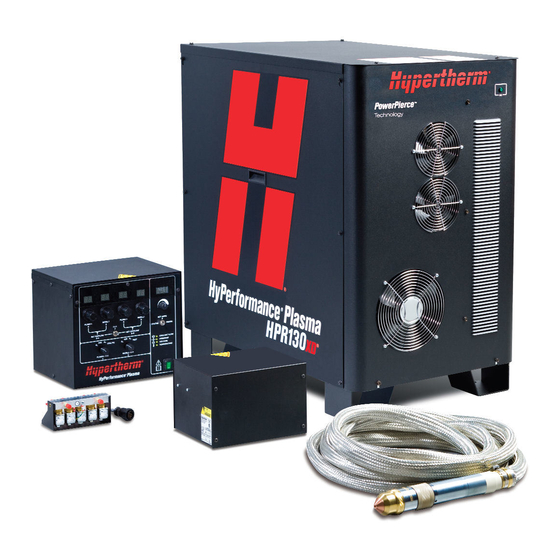
Hypertherm HPR130 Instruction Manual (239 pages)
Brand:
Hypertherm
| Category:
Welding System
| Size: 23.78 MB
Table of Contents
English
9
Electromagnetic Compatibility (EMC
5
Assessment of Area
5
Warranty
7
Patent Indemnity
7
Table of Contents
9
Safety
15
Recognize Safety Information
16
Follow Safety Instructions
16
Cutting Can Cause Fire or Explosion
16
Electric Shock Can Kill
17
Static Electricity Can Damage Circuit Boards
17
Toxic Fumes Can Cause Injury or Death
18
A Plasma Arc Can Cause Injury and Burns
19
Arc Rays Can Burn Eyes and Skin
19
Grounding Safety
19
Compressed Gas Equipment Safety
20
Gas Cylinders Can Explode if Damaged
20
Noise Can Damage Hearing
20
Pacemaker and Hearing Aid Operation
20
A Plasma Arc Can Damage Frozen Pipes
20
Additional Safety Information
20
Warning Labels
22
Français
23
Sécurité
23
Section 1A
23
Identifier Les Consignes de Sécurité
24
Le Coupage Peut Provoquer un Incendie Ou Une Explosion
24
Suivre Les Instructions de Sécurité
24
L'électricité Statique Peut Endommager Les Cartes de Circuits Imprimés
25
Les Chocs Électriques Peuvent Être Fatals
25
Les Vapeurs Toxiques Peuvent Provoquer des Blessures Ou la Mort
26
L'arc Plasma Peut Provoquer des Blessures Ou des Brûlures
27
Les Rayons de L'arc Peuvent Brûler Les Yeux Et la Peau
27
Mise À la Masse Et À la Terre
27
Le Bruit Peut Provoquer des Problèmes Auditifs
28
Les Bouteilles de Gaz Comprimé Peuvent Exploser en Cas de Dommages
28
Pacemakers Et Prothèses Auditives
28
Sécurité des Bouteilles de Gaz Comprimé
28
Un Arc Plasma Peut Endommager Les Tuyaux Gelés
28
Étiquettes de Sécurité
30
Español
31
Seguridad
31
Section 1B SEGURIDAD
31
Reconocimiento de Información de Seguridad
32
Siga las Instrucciones de Seguridad
32
Los Cortes Pueden Provocar Incendios O Explosiones
32
El Choque Eléctrico Puede Provocar la Muerte
33
Electricidad Estática Puede Dañar Tablillas de Circuito
33
Humos Tóxicos Pueden Causar Lesiones O Muerte
34
El Arco de Plasma Puede Causar Lesiones y Quemaduras
35
Los Rayos del Arco Pueden Producir Quemaduras en Los Ojos y en la Piel
35
Seguridad de Toma a Tierra
35
Seguridad de Los Equipos de Gas Comprimido
36
Los Cilindros de Gas Pueden Explotar si Están Dañados
36
El Ruido Puede Deteriorar la Audición
36
Operación de Marcapasosy de Audífonos
36
Un Arco Plasma Puede Dañar Tubos Congelados
36
Etiquetas de Advertencia
37
Specifications
39
Section 2 SPECIFICATIONS
39
System Description
41
General
41
Power Supply
41
Ignition Console
41
Gas Console
41
Off-Valve
41
Torch
41
Specifications
42
System Gas Requirements
42
Power Supply
43
Ignition Console - 078172
44
Gas Consol - 078170
46
Gas Console - 078170
46
Off-Valve - 129816
47
Torch - 128818
48
Installation
49
Section 3 INSTALLATION
49
Upon Receipt
51
Claims
51
Installation Requirements
51
Noise Levels
51
Placement of System Components
51
Torque Specifications
51
Installation Requirements
52
System Components
53
Cables and Hoses
53
Supply Gas Hoses
53
Customer Supplied Power Cable
53
Recommended Grounding and Shielding Practices
54
Introduction
54
Types of Grounding
54
Steps to Take
55
Placement of the Power Supply
59
Install the Ignition Console
60
Placement of the Gas Console
62
Install the Off-Valve
63
Power Supply to Ignition Console Leads
64
Pilot Arc Lead
64
Negative Lead
64
Ignition Console Power Cable
66
Ignition Console Coolant Hoses
67
Power Supply to Gas Console Cables
68
Control Cable
68
Power Cable
68
Gas Console to Off-Valve Connections
70
Cable and Gas Hose Assembly
70
Gas Console to Off-Valve Cable
70
Off-Valve Cable
70
Power Supply to CNC Interface Cable
72
Optional Multi-System CNC Interface Cable
72
Notes to CNC Interface Cable Run List
73
Examples of Output Circuits
74
Examples of Input Circuits
75
Remote On/Off Switch
76
Torch Lead Assembly
77
Work Lead
78
Torch Connections
79
Connect the Torch to the Torch Lead Assembly
79
Connect the Torch to the Quick-Disconnect
82
Torch Mounting and Alignment
83
Mounting the Torch
83
Torch Alignment
83
Torch Lifter Requirement
83
Power Requirements
84
General
84
Line Disconnect Switch
84
Power Cable
84
Connect the Power
85
Torch Coolant Requirements
86
Standard Installation
86
Coolant for Cold Operating Temperatures
87
Coolant for Hot Operating Temperatures
88
Water Purity Requirements
88
Fill the Power Supply with Coolant
89
Gas Requirements
90
Setting the Supply Regulators
90
Gas Regulators
91
Supply Gas Plumbing
92
Connect the Supply Gases
92
Supply Gas Hoses
93
Operation
94
Section 4 OPERATION
94
Daily Start-Up
95
Check Torch
95
Controls and Indicators
96
General
96
Main Power Switch
96
Power Indicators
96
Manual Gas Console Operation
97
Consumable Selection
98
Mild Steel
98
Stainless Steel
98
Aluminum
99
Install Consumables
100
Cut Charts
101
Bevel Cutting
101
Marking
101
Consumables for Mirror-Image Cutting
101
Estimated Kerf Width Compensation
102
Changing Consumable Parts
115
Remove Consumables
115
Inspect Consumables
116
Inspect Torch
117
Inspect Electrode Pit Depth
118
Replace Torch Water Tube
119
Common Cutting Faults
120
How to Optimize Cut Quality
121
Tips for Table and Torch
121
Plasma Set-Up Tips
121
Maximize the Life of Consumable Parts
121
Additional Factors of Cut Quality
122
Additional Improvements
123
Maintenance
124
Section 5 MAINTENANCE
124
Iintroduction
126
Routine Maintenance
126
Introduction
126
System Description
127
Control and Signal Cables
127
Sequence of Operation
128
Gas System Valve Usage
129
Gas System Purge Cycle
129
Error Codes
133
Error Code Troubleshooting - 10 of 10
134
Error Code Troubleshooting - 1 of 10
135
Error Code Troubleshooting - 2 of 10
136
Error Code Troubleshooting - 3 of 10
137
Error Code Troubleshooting - 4 of 10
138
Error Code Troubleshooting - 5 of 10
139
Error Code Troubleshooting - 6 of 10
140
Error Code Troubleshooting - 7 of 10
141
Error Code Troubleshooting - 8 of 10
142
Error Code Troubleshooting - 9 of 10
143
Power Supply States
144
Plasma System Operation with Pump Timeout
145
CNC Operation with Pump Timeout
146
Initial Checks
147
Power Measurement
148
Power Supply Coolant System Servicing
149
Draining the Coolant System
149
Coolant System Filter and Strainer
150
Filter Replacement
150
Pump Strainer Cleaning
150
Coolant Flow Troubleshooting Chart
151
Coolant Flow Tests
152
Before Testing
152
Using the Hypertherm Flow Meter (128933)
152
Manual Pump Operation
153
Test 1 - Return Line
154
Test 2 - Supply Line at Ignition Console
154
Test 3 - Change the Torch
155
Test 4 - Supply Line to the Torch Receptacle
155
Test 5 - Return Line from the Torch Receptacle
155
Test 6 - Bucket Test at the Pump
156
Test 7 - Bypass the Check Valve
156
Pump and Motor Troubleshooting
157
Testing the Flow Switch
158
Gas Leak Tests
159
Power Supply Control Board PCB3
160
Power Supply Power Distribution Board PCB2
161
Start Circuit PCB1
162
Operation
162
Start Circuit Functional Schematic
162
Start Circuit Troubleshooting
162
Pilot Arc Current Levels
164
Gas Console Control Board PCB2
165
Gas Console Power Distribution Board PCB1
166
Gas Console AC Valve-Driver Board PCB3
167
Chopper Tests
168
Phase-Loss Detection Test
170
Torch Lead Test
171
Preventive Maintenance
172
Cooling System
173
Power Supply
176
Section 6 PARTS LIST
179
Power Supply
180
Ignition Console
185
Gas Console - 1 of 2
186
Gas Console - 2 of 2
187
Off-Valve
187
Hyperformance Torch
188
Torch Assembly
188
Torch Leads
188
Consumable Parts Kit - 128878
189
Consumables for Mirror-Image Cutting
190
Recommended Spare Parts
191
Wiring Diagrams
192
Introduction
192
Section 7 WIRING DIAGRAMS
192
Appendix A PROPYLENE GLYCOL SAFETY DATA / BENZOTRIAZOLE SAFETY DATA
214
Section 1 Chemical Product and Company Identification
214
Section 2 Composition / Information on Ingredients
214
Section 3 Hazards Identification
214
Chemical Product and Company Identification
214
Information on Ingredients
214
Hazards Identification
214
Section 4 First Aid Measures
215
Section 5 Fire Fighting Measures
215
Section 6 Accidental Release Measures
215
Section 7 Handling and Storage
215
First Aid Measures
215
Fire Fighting Measures
215
Accidental Release Measures
215
Handling and Storage
215
Section 8 Exposure Controls / Personal Protection
216
Section 9 Physical and Chemical Properties
216
Section 10 Stability and Reactivity
216
Section 11 Toxicological Information
216
Exposure Controls / Personal Protection
216
Physical and Chemical Properties
216
Stability and Reactivity
216
Toxicological Information
216
Section 12 Ecological Information
217
Section 13 Disposal Considerations
217
Section 14 Transport Information
217
Section 15 Regulatory Information
217
Section 16 Other Information
217
Ecological Information
217
Disposal Considerations
217
Transport Information
217
Regulatory Information
217
Other Information
217
Freezing Point of Propylene Glycol Solution
218
Software Functional Description
220
Appendix Cbevel CUTTING
224
Bevel Torch Dimensions
224
Bevel Cutting Definitions
225
Cut Charts
226
Torch Connections
229
Connect the Torch Lead Assembly to the Quick-Disconnect Assembly
229
Parts List
231
Consumables
231
Part Selection
232
Appendix B SOFTWARE FUNCTIONAL DESCRIPTION
235
Advertisement
Hypertherm HPR130 Instruction Manual (191 pages)
HyPerformance Plasma
Brand:
Hypertherm
| Category:
Welding System
| Size: 17.62 MB
Table of Contents
English
6
Electromagnetic Compatibility (EMC
4
Warranty
5
General
5
Patent Indemnity
5
Limitation of Liability
5
Liability Cap
5
Insurance
5
National and Local Codes
5
Transfer of Rights
5
Table of Contents
6
Safety
11
Recognize Safety Information
12
Follow Safety Instructions
12
Cutting Can Cause Fire or Explosion
12
Electric Shock Can Kill
13
Cutting Can Produce Toxic Fumes
13
A Plasma Arc Can Cause Injury and Burns
14
Arc Rays Can Burn Eyes and Skin
14
Grounding Safety
14
Compressed Gas Equipment Safety
15
Gas Cylinders Can Explode if Damaged
15
Noise Can Damage Hearing
15
Pacemaker and Hearing Aid Operation
15
A Plasma Arc Can Damage Frozen Pipes
15
Additional Safety Information
15
Warning Label
16
Français
18
Section 1A
18
Sécurité
18
Danger Avertissement Précaution
19
Risque D'explosion Argon-Hydrogène Et Méthane
19
Détonation de L'hydrogène Lors du Coupage de L'aluminium
19
Les Chocs Électriques Peuvent Être Fatals
20
Le Coupage Peut Produire des Vapeurs Toxiques
20
Prévention des Chocs Électriques
20
L'arc Plasma Peut Provoquer des Blessures Ou des Brûlures
21
Mise À la Masse Et À la Terre
21
Les Rayons de L'arc Peuvent Brûler Les Yeux Et la Peau
21
Torches À Allumage Instantané
21
Sécurité des Bouteilles de Gaz Comprimé
22
Les Bouteilles de Gaz Comprimé Peuvent Exploser en Cas de Dommages
22
Le Bruit Peut Provoquer des Problèmes Auditifs
22
Pacemakers Et Prothéses Auditives
22
Un Arc Plasma Peut Endommager Les Tuyaux Gelés
22
Identifier Les Consignes de Sécurité
19
Le Coupage Peut Provoquer un Incendie Ou Une Explosion
19
Suivre Les Instructions de Sécurité
19
Pacemakers Et Prothèses Auditives
22
Étiquette de Sécurité
23
Specifications
25
Section 2 SPECIFICATIONS
25
System Description
27
General
27
Power Supply
27
HPR130 Manual Gas Instruction Manual
27
Ignition Console
27
Gas Console
27
Off-Valve
27
Torch
27
Specifications
28
System Gas Requirements
28
Power Supply
29
Ignition Console - 078172
30
Gas Consol - 078170
32
Gas Console - 078170
32
Off-Valve - 129816
33
Torch - 128818
34
Installation
35
Section 3 INSTALLATION
35
Upon Receipt
37
Claims
37
Installation Requirements
37
Noise Levels
37
Placement of System Components
37
Torque Specifications
37
Installation Requirements
38
System Components
39
Cables and Hoses
39
Supply Gas Hoses
39
Customer Supplied Power Cable
39
System Grounding Requirements
40
Suggested Ground Cable Routing
40
Power Supply
40
Equipment Grounding
40
Work Table Grounding
41
Placement of the Power Supply
43
Install the Ignition Console
44
Placement of the Gas Console
46
Install the Off-Valve
47
Power Supply to Ignition Console Leads
48
Pilot Arc Lead
48
Negative Lead
48
Ignition Control Cable
50
Ignition Console Coolant Hoses
51
Power Supply to Gas Console Cables
52
Control Cable
52
Power Cable
52
Gas Console to Off-Valve Connections
54
Cable and Gas Hose Assembly
54
Gas Console to Off-Valve Cable
54
Off-Valve Cable
54
Power Supply to CNC Interface Cable
56
Optional Multi-System CNC Interface Cable
56
Notes to CNC Interface Cable Run List
57
Examples of Output Circuits
58
Examples of Input Circuits
59
Remote On/Off Switch
60
Torch Lead Assembly
61
Work Lead
62
Torch Connections
63
Connect the Torch to the Torch Lead Assembly
63
Connect the Torch to the Quick-Disconnect
65
Torch Mounting and Alignment
66
Torch Lifter Requirement
66
Power Requirements
67
General
67
Line Disconnect Switch
67
Power Cable
67
Connect the Power
68
Torch Coolant Requirements
69
Water Purity Requirements
69
Fill the Power Supply with Coolant
70
Gas Requirements
71
Setting the Supply Regulators
71
Gas Regulators
72
Supply Gas Plumbing
73
Connect the Supply Gases
73
Supply Gas Hoses
74
Operation
75
Section 4 OPERATION
75
Daily Start-Up
76
Check Torch
76
Controls and Indicators
77
General
77
Main Power Switch
77
Power Indicators
77
Manual Gas Console Operation
78
Consumable Selection
79
Mild Steel
79
Stainless Steel
79
Aluminum
80
Install Consumables
81
Cut Charts
82
Marking
82
Consumables for Mirror-Image Cutting
82
Estimated Kerf Width Compensation
83
Changing Consumable Parts
95
Remove Consumables
95
Inspect Consumables
96
Inspect Torch
97
Inspect Electrode Pit Depth
98
Replace Torch Water Tube
99
Common Cutting Faults
100
How to Optimize Cut Quality
101
Tips for Table and Torch
101
Plasma Set-Up Tips
101
Maximize the Life of Consumable Parts
101
Additional Factors of Cut Quality
102
Additional Improvements
103
Maintenance
104
Section 5 MAINTENANCE
104
Introduction
105
Routine Maintenance
105
System Description
106
Control and Signal Cables
106
Sequence of Operation
107
Error Codes
109
Error Code Troubleshooting - 1 of 6
110
Error Code Troubleshooting - 2 of 6
111
Error Code Troubleshooting - 3 of 6
112
Error Code Troubleshooting - 4 of 6
113
Error Code Troubleshooting - 5 of 6
114
Error Code Troubleshooting - 6 of 6
115
Power Supply States
116
Plasma System Operation with Pump Timeout
117
CNC Operation with Pump Timeout
118
Initial Checks
119
Power Measurement
120
Power Supply Coolant System Servicing
121
Draining the Coolant System
121
Coolant System Filter and Strainer
122
Filter Replacement
122
Pump Strainer Cleaning
122
Coolant Flow Test Procedure
123
Testing the Flow Switch
124
Gas Leak Test Procedure
125
Power Supply Control Board PCB3
126
Power Supply Power Distribution Board PCB2
127
Start Circuit PCB1
128
Operation
128
Start Circuit Functional Schematic
128
Start Circuit Troubleshooting
128
Pilot Arc Current Levels
130
Gas Console Control Board PCB2
131
Gas Console Power Distribution PCB1
132
Gas Console AC Valve-Driver PCB3
133
Chopper Module Test Procedure
134
Phase-Loss Detection Test
136
Torch Lead Test
137
Preventive Maintenance
138
Power Supply
142
Section 6 PARTS LIST
145
Power Supply
146
Ignition Console
150
Gas Console - 1 of 2
151
Gas Console - 2 of 2
152
Off-Valve
152
Hyperformance Torch
153
Torch Assembly
153
Torch Leads
153
Consumable Parts Kit - 128878
154
Consumables for Mirror-Image Cutting
155
Recommended Spare Parts
156
Wiring Diagrams
157
Introduction
157
Section 7 WIRING DIAGRAMS
157
Software Functional Description
179
Appendix A SOFTWARE FUNCTIONAL DESCRIPTION
182
Propylene Glycol Safety Data / Benzotriazole Safety Data
182
Appendix B PROPYLENE GLYCOL SAFETY DATA / BENZOTRIAZOLE SAFETY DATA
183
Section 1 Chemical Product and Company Identification
183
Section 2 Composition / Information on Ingredients
183
Section 3 Hazards Identification
183
Section 4 First Aid Measures
184
Section 5 Fire Fighting Measures
184
Section 6 Accidental Release Measures
184
Section 7 Handling and Storage
184
Section 8 Exposure Controls / Personal Protection
185
Section 9 Physical and Chemical Properties
185
Section 10 Stability and Reactivity
185
Section 11 Toxicological Information
185
Section 12 Ecological Information
186
Section 13 Disposal Considerations
186
Section 14 Transport Information
186
Section 15 Regulatory Information
186
Section 16 Other Information
186
Freezing Point of Propylene Glycol Solution
187
Hypertherm HPR130 Instruction Manual (32 pages)
Brand:
Hypertherm
| Category:
Welding System
| Size: 3.13 MB
Table of Contents
Table of Contents
7
Preventive Maintenance Program
9
Overview
9
Cleaning and Inspection Schedule
10
Daily
11
Do a Test of the Inlet Pressures
11
Examine All of the Air Filters
11
Do a Check of the Coolant Level and Condition
12
Examine and Lubricate O-Rings
13
Examine the Water Tube and Torch
13
Weekly
14
Examine Hoses and Torch Leads
14
Do Tests for Gas Leaks
14
Do a Check of the Coolant Flow
14
Do a Check of the Coolant Level
14
Monthly
15
Clean Inside the Power Supply
15
Examine the Coolant System
15
Examine the Main Contactor
16
Examine the Pilot Arc Relay
16
Do the Coolant Flow Test
16
Examine the Gas Line Connections
17
Examine the Hoses
17
Examine the Cables
17
Examine the Ground Connections
17
Examine the Table-To-Workpiece Connection
17
Component Replacement Schedule
18
Cutting Area and Operation Effects
21
External Cutting Area
21
Incoming Air Supply Quality
22
Metal Dust Inside the Power Supply Cabinet
22
Consumable Use
23
Cut-Cycle Time
24
Find Arc Hour Data on a Hypertherm CNC
25
Part Numbers for HPR130 Manual Gas Cables and Leads
26
Power Supply to Ignition Console Leads
26
Pilot Arc Lead
26
Negative Lead
26
Ignition Console Power Cable
26
Ignition Console Coolant Hose
27
Power Supply to Gas Console Cables
27
Control Cable
27
Power Cable
27
Cable and Gas Hose Assembly (Gas Console to Off-Valve)
27
Power Supply to CNC Interface Cable
28
Torch Lead
28
Work Lead
28
Supply Gas Hoses
29
Air Hose
29
Argon-Hydrogen (H35) or Nitrogen-Hydrogen (F5) Hose
29
Nitrogen or Argon Hose
29
Oxygen Hose
29
System Information
30
Model Number
30
Serial Number
30
System Voltage
30
Coolant Requirements
30
Notes
31
Maintenance Log for HPR130 Manual Gas Plasma Systems
32
Advertisement
Hypertherm HPR130 Field Service Bulletin (6 pages)
Control Board Replacement
Brand:
Hypertherm
| Category:
Power Supply
| Size: 0.19 MB
Advertisement
Related Products
Hypertherm HyPerformance HPR130XD
Hypertherm HPRXD Series
Hypertherm HT40C
Hypertherm HT4100
Hypertherm HT2000LHF
Hypertherm H65
Hypertherm H65s
Hypertherm H85
Hypertherm H85s
Hypertherm HyPerformance Plasma HPR260
Hypertherm Categories
Welding System
Cutter
Flashlight
Industrial Equipment
Water Pump
More Hypertherm Manuals
Login
Sign In
OR
Sign in with Facebook
Sign in with Google
Upload manual
Upload from disk
Upload from URL