Sign In
Upload
Manuals
Brands
Hypertherm Manuals
Cutter
HyDefinition HD4070
Hypertherm HyDefinition HD4070 Manuals
Manuals and User Guides for Hypertherm HyDefinition HD4070. We have
3
Hypertherm HyDefinition HD4070 manuals available for free PDF download: Instruction Manual, Product Configuration Manual, Field Service Bulletin
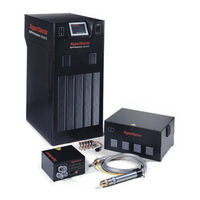
Hypertherm HyDefinition HD4070 Instruction Manual (265 pages)
Plasma Arc Cutting / Marking System
Brand:
Hypertherm
| Category:
Cutter
| Size: 17 MB
Table of Contents
English
8
Electromagnetic Compatibility (EMC
6
General
7
Insurance
7
Liability Cap
7
Limitation of Liability
7
National and Local Codes
7
Patent Indemnity
7
Transfer of Rights
7
Table of Contents
8
Warranty
7
Safety
14
Recognize Safety Information
15
Follow Safety Instructions
15
Cutting Can Cause Fire or Explosion
15
Electric Shock Can Kill
16
Cutting Can Produce Toxic Fumes
16
A Plasma Arc Can Cause Injury and Burns
17
Arc Rays Can Burn Eyes and Skin
17
Grounding Safety
17
Compressed Gas Equipment Safety
18
Gas Cylinders Can Explode if Damaged
18
Noise Can Damage Hearing
18
Pacemaker and Hearing Aid Operation
18
A Plasma Arc Can Damage Frozen Pipes
18
Additional Safety Information
18
Warning Label
19
Français
20
Section 1A
20
Sécurité
20
Danger Avertissement Précaution
21
Risque D'explosion Argon-Hydrogène Et Méthane
21
Détonation de L'hydrogène Lors du Coupage de L'aluminium
21
Les Chocs Électriques Peuvent Être Fatals
22
Le Coupage Peut Produire des Vapeurs Toxiques
22
Prévention des Chocs Électriques
22
L'arc Plasma Peut Provoquer des Blessures Ou des Brûlures
23
Mise À la Masse Et À la Terre
23
Les Rayons de L'arc Peuvent Brûler Les Yeux Et la Peau
23
Torches À Allumage Instantané
23
Sécurité des Bouteilles de Gaz Comprimé
24
Les Bouteilles de Gaz Comprimé Peuvent Exploser en Cas de Dommages
24
Le Bruit Peut Provoquer des Problèmes Auditifs
24
Pacemakers Et Prothéses Auditives
24
Identifier Les Consignes de Sécurité
21
Le Coupage Peut Provoquer un Incendie Ou Une Explosion
21
Suivre Les Instructions de Sécurité
21
Pacemakers Et Prothèses Auditives
24
Un Arc Plasma Peut Endommager Les Tuyaux Gelés
24
Étiquette de Sécurité
25
Specifications
26
Section 2 Specifications
26
System Description
27
General
27
Power Supply
27
Machine Torch
27
Off-Valve Assembly
28
Gas Console
28
Ignition Console
28
Options
28
Options - Continued
29
Specifications
30
System Gas Requirements
30
Power Supply
31
Gas Console Assembly
33
Ignition Console Assembly
34
Off-Valve Assembly
35
Torch Specifications
36
X-Y Lifter Assembly
37
Torch Breakaway Kit
38
Installation
39
Section 3 Installation
39
Upon Receipt
40
Claims
40
Installation Requirements
40
Gas Requirements
40
Torch Coolant Requirements
41
Water Purity Requirements
42
Noise Levels
42
Torch Lifter Requirement
42
Placement of System Components
43
HD4070 Installation - Basic Requirements
44
Place System Components
45
Customer-Supplied Cables and Hoses
45
Install Cables and Hoses
45
Remote Display Option
45
Placement of the Power Supply
46
Placement of the Gas Console Assembly
47
Mount the Ignition Console Assembly
48
Install the Off-Valve Assembly
49
Grounding Requirements
50
Supply Gas Plumbing
51
Connect the Supply Gases
51
Power Requirements
52
General
52
Line Disconnect Switch
52
Power Cable
52
Connect the Power
53
Install the Power Supply to Gas Console and CNC Cables
54
Signal Cable - Power Supply to Gas Console
55
Power Cable - Power Supply to Gas Console
55
CNC Interface Cable - Power Supply to CNC
56
Install the Remote Display Cable
58
Remote Display
58
Signal Cable - Power Supply to Remote Display
58
Display Mounting Dimensions
59
Section 3A
60
HD4070 1-Torch Installation
61
System Components
62
Cables and Hoses
62
Install the Coolant Hoses
63
Coolant Hose Assembly - Green Supply
64
Coolant Hose Assembly - Red Return
64
Install the Power Supply to Ignition Console Leads
65
Install the Work Lead
65
Pilot Arc Lead
66
Negative Lead
66
Work Lead
66
Install the Gas Console to Ignition Console Cable
67
Cable - Gas Console to Ignition Console
68
Install the Ignition Console to Off-Valve Cable and Gas Hose Assembly
69
Hoses - Gas Console to Off-Valve
70
Cable - Ignition Console to Off-Valve
70
Cable - Off-Valve
70
THC and Torch Installation
71
X-Y Lifter Assembly
71
Torch Mounting Block Kit
72
Torch Breakaway Kit (Optional)
73
Install the Torch (Without Torch Breakaway Option)
75
Install the Torch (Without Torch Breakaway)
75
Install the Torch (with Torch Breakaway Option)
76
Install the Torch (with Torch Breakaway)
76
Integrated Command THC Option - Cable Installation
77
Integrated Command THC Option- Cable Installation
77
Cable - Lifter Interface
78
Cable - Motor Drive
78
Ohmic Contact Wire
78
Lifter Interface Cable Signals
79
Motor Drive Cable Signals
79
Torch Connections
80
Connecting the Torch to Torch Leads
80
Torch Mounting and Alignment
81
Install the Torch and Lead Assembly
82
Torch and Lead Assembly
82
Fill the Power Supply with Coolant
83
Section 3B
85
HD4070 2-Torch Installation
86
System Components
87
Cables and Hoses
87
Install the Coolant Hoses
88
Coolant Hose Assembly - Green Supply
89
Coolant Hose Assembly - Red Return
89
Install the Pilot Arc Leads
90
Pilot Arc Lead
91
Install the Negative and Work Leads
92
Negative Lead
93
Work Lead
93
Install the Gas Console to Ignition Console Cable
94
Cable - Gas Console to Ignition Console
95
Install the Gas Hose Assembly
96
Hoses - Gas Console to Off-Valve
97
Install the Ignition Console to Off-Valve Cables
98
Cable - Ignition Console to Off-Valve
99
Cable - Off-Valve
99
Install the Integrated Command THC Option
100
Cable - Lifter Interface
101
Cable - Motor Drive
101
Ohmic Contact Wire
101
Lifter Interface Cable Signals
102
Motor Drive Cable Signals
102
Torch Connections
103
Connecting the Torch to Torch Leads
103
Torch Mounting and Alignment
104
Install the Torch and Lead Assembly
105
Torch and Lead Assembly
105
Fill the Power Supply with Coolant
106
Section 4 Operation
108
Power Supply Controls and Indicators
109
General
109
Power Switch
109
Power Indicators
109
Power Supply Display
110
System Setup Screens Navigation
111
System Operation Screens Navigation
113
Daily Start-Up
114
Check Torch
114
Turn Power Supply on
115
System Setup Screens
115
System Operation Screens
118
Consumables Selection
121
Install Consumables
122
Cut Charts
123
Changing Consumable Parts
136
Remove Consumables
136
Inspect Consumables
137
Inspect Torch
138
Inspect Electrode Pit Depth
139
Replace Torch Water Tube
140
Common Cutting Faults
141
Cutting Techniques
142
How to Get Better Cut Quality
142
How to Get Longer Consumable Life
144
How to Get Better Pierces
145
How to Increase Cutting Speed
145
Technical Questions
145
Maintenance
146
Section 5 Maintenance
146
Introduction
147
Routine Maintenance
147
HD4070 System Description
148
Control and Signal Cables
148
Power Supply Coolant System Servicing
149
Torch Coolant Draining
151
Power Supply Coolant Draining
151
Coolant System Filter and Strainer
152
Coolant Flow Test Procedure
154
HD4070 Process Sequence
155
Initial Checks
157
Power Measurement
158
Service Display Screens
159
Error Codes
160
Electrical PC Boards and Power Supplies
162
Plasma Interface Board PCB5 Status Indicators
166
Breakout Board PCB6 Status Indicators
167
Control Board PCB3 Status Indicators
171
Power Distribution Board PCB4 Status Indicators
172
Start Circuit Assembly Board PCB2
173
Pilot Arc Current Levels
173
Start Circuit Functional Schematic
174
Start Circuit Troubleshooting
174
Gas Console Relay Board PCB1
175
Gas Console Relay Board PCB3
177
Gas Console Control Board PCB2
179
Leak Test Procedure
180
Chopper Module Test Procedure
181
Phase Loss Detection Board PCB1 Status Indicators and Operation
183
THC Routine Maintenance
184
X-Y Lifter Sealing Band- Replace
184
THC Motor Drive Board
188
THC Power Supply
189
THC Control Board
190
Preventive Maintenance Schedule
192
Parts List
193
Section 6 Parts List
193
Power Supply
194
Front Panel Outside
194
Left Side Interior
195
Right Side Interior
196
PC Boards and Interlock Switches
197
I/O Panel
198
Cooling System
200
Ignition Console
201
Gas Console - 1 of 2
202
Gas Console - 2 of 2
203
HD4070 Torch
204
Consumable Configurations
205
Consumable Parts Kit
206
Off-Valve Assembly
207
Recommended Spare Parts
207
Integrated Command THC
209
X-Y Lifter Assembly
209
X-Y Lifter Torch Mounting Block Kit
210
X-Y Lifter Breakaway Kit - Optional
211
Ohmic Contact Wire
212
Wiring Diagrams
219
Introduction
219
Wiring Diagram Symbols
219
Appendix A System Grounding
236
System Grounding Requirements
236
Suggested Ground Cable Routing
236
Power Supply
236
Equipment Grounding
236
Work Table Grounding
237
Appendix B Propylene Glycol Safety Data
240
Benzotriazole Safety Data
240
Appendix C Gas Regulators
250
Appendix D Service Screen (#18) Status Table
252
Appendix E Integrated Command THC Supplemental Information
255
Command THC Serial Protocol
255
CNC Serial Interface
257
Appendix Fpc-104 Stack: Jumper Positions
263
Advertisement
Hypertherm HyDefinition HD4070 Product Configuration Manual (88 pages)
Plasma Arc Cutting / Marking System
Brand:
Hypertherm
| Category:
Welding System
| Size: 3 MB
Table of Contents
Table of Contents
4
Description
5
General
5
Power Supply
5
Machine Torch
5
Off-Valve Assembly
5
Gas Console
5
Ignition Console
5
Options
6
Specifications
10
System Requirements
10
Power Supply
11
Gas Console Assembly - 078085
13
Ignition Console Assembly - 078088
14
Off-Valve Assembly - 129563
15
Machine Torch Assembly with Leads
16
Ordering the HD4070 System
19
Hypertherm HyDefinition HD4070 Field Service Bulletin (8 pages)
Power Supply Display Removal And Remote Installation Kit
Brand:
Hypertherm
| Category:
Welding System
| Size: 1 MB
Table of Contents
Kit Contents
3
Purpose
3
Electric Shock Can Kill
4
Procedure
4
Display - Remote Installation Kit Instructions
4
Static Electricity Can Damage Circuit Boards
5
Static Electricity Warning
5
Mounting the Remote Display
7
Installation Notes
8
Advertisement
Advertisement
Related Products
Hypertherm HyDefinition HD3070
Hypertherm HT4001
Hypertherm HT4400
Hypertherm HyPerformance Plasma HPR260
Hypertherm HyPerformance HPR400XD
Hypertherm HyPerformance Plasma HPR800XD
Hypertherm HyPerformance Plasma HPR400
Hypertherm HPR130
Hypertherm HyDefinition
Hypertherm H65s
Hypertherm Categories
Welding System
Cutter
Flashlight
Industrial Equipment
Water Pump
More Hypertherm Manuals
Login
Sign In
OR
Sign in with Facebook
Sign in with Google
Upload manual
Upload from disk
Upload from URL