Sign In
Upload
Manuals
Brands
Hypertherm Manuals
Welding System
HyPerformance HPR130XD
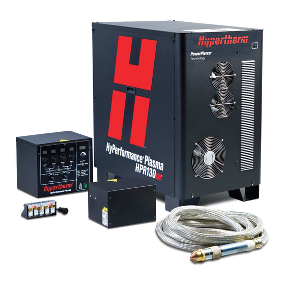
Hypertherm HyPerformance HPR130XD Manuals
Manuals and User Guides for Hypertherm HyPerformance HPR130XD. We have
1
Hypertherm HyPerformance HPR130XD manual available for free PDF download: Instruction Manual
Hypertherm HyPerformance HPR130XD Instruction Manual (302 pages)
Auto gas
Brand:
Hypertherm
| Category:
Welding System
| Size: 26.76 MB
Table of Contents
Assessment of Area
5
Electromagnetic Compatibility (Emc)
5
Electromagnetic Compatibility Emc
7
Warranty
7
Patent Indemnity
7
Table of Contents
9
Section 1
18
Safety
18
Recognize Safety Information
18
Follow Safety Instructions
18
Inspect Equipment before Using
18
Responsibility for Safety
18
A Plasma Arc Can Damage Frozen Pipes
18
Static Electricity Can Damage Printed Circuit Boards
18
Grounding Safety
19
Electrical Hazards
19
Electric Shock Can Kill
19
Cutting Can Cause Fire or Explosion
20
Machine Motion Can Cause Injury
20
Compressed Gas Equipment Safety
21
Gas Cylinders Can Explode if Damaged
21
Toxic Fumes Can Cause Injury or Death
21
A Plasma Arc Can Cause Injury and Burns
22
Arc Rays Can Burn Eyes and Skin
22
Pacemaker and Hearing Aid Operation
22
Noise Can Damage Hearing
23
Dry Dust Collection Information
23
Laser Radiation
24
Additional Safety Information
24
Section 2
25
Specifications
25
System Description
27
General
27
Power Supply
27
Ignition Console
27
Selection Console
27
Metering Console
27
Torch
27
Specifications
28
System Gas Requirements
28
Power Supply
29
Ignition Console - 078172
30
Torch Lead Junction Box (Optional) - 078619
32
Selection Console - 078533
33
Metering Console - 078535
34
Torch - 228520
35
IEC Symbols
36
Symbols and Marks
37
Section 3
39
Installation
39
Upon Receipt
41
Claims
41
Installation Requirements
41
Noise Levels
41
Placement of System Components
41
Torque Specifications
41
Installation Requirements
42
System Components
43
Cables and Hoses
43
Supply Gas Hoses
43
Customer-Supplied Power Cable
43
Recommended Grounding and Shielding Practices
44
Introduction
44
Types of Grounding
44
Grounding Practices
44
Grounding Diagram
47
Placement of the Power Supply
49
Install the Ignition Console
50
Install the Metering Console
52
Placement of the Selection Console
53
Power Supply to Ignition Console Leads
54
Pilot Arc Lead
54
Negative Lead
54
Ignition Console Power Cable
56
Ignition Console Coolant Hoses
57
Power Supply to Selection Console Cables
58
Control Cable
58
Power Cable
58
Selection Console to Metering Console Connections
60
Cable and Gas Hose Assembly
60
Power Supply to CNC Interface Cable
62
Optional Multi-System CNC Interface Cable
62
Notes to CNC Interface Cable Run List
63
HPR130XD Auto Gas - 806330
63
Examples of Output Circuits
64
Examples of Input Circuits
65
Remote ON/OFF Switch (Provided by Customer)
66
Torch Lead Assembly
67
Torch Lead Junction Box (Optional)
68
Install the Junction Box
69
Connect the Leads
70
Work Lead
74
Torch Connections
75
Connect the Torch to the Torch Lead Assembly
75
Connect the Torch to the Quick-Disconnect
79
Torch Mounting and Alignment
80
Mounting the Torch
80
Torch Alignment
80
Torch Lifter Requirement
81
Hypernet
81
Power Requirements
82
General
82
Line Disconnect Switch
83
Main Power Cable
83
Connect the Power
84
Torch Coolant Requirements
85
Premixed Coolant for Standard Operating Temperatures
85
Custom Coolant MIX for Cold Operating Temperatures
86
Custom Coolant MIX for Hot Operating Temperatures
87
Water Purity Requirements
87
Fill the Power Supply with Coolant
88
Gas Requirements
89
Setting the Supply Regulators
89
Gas Regulators
90
Supply Gas Plumbing
91
Connect the Supply Gases
92
Supply Gas Hoses
93
Section 4
95
Operation
95
Daily Start-Up
97
Check Torch
97
Power Indicators
98
General
98
Power Supply
98
Selection Console
98
Metering Console
98
CNC Controller Requirements
99
Base Required Elements
99
Required Real Time Elements
99
Required Diagnostic Elements
99
CNC Screen Examples
100
Main (Control) Screen
100
Diagnostics Screen
101
Test Screen
102
Cut Chart Screen
103
Consumable Selection
104
Standard Cutting (0°)
104
Bevel Cutting (0° to 45°)
104
Marking
104
Consumables for Mirror-Image Cutting
104
Silverplus Electrodes
104
Mild Steel
105
Stainless Steel
105
Aluminum
106
Mild Steel Bevel Cutting
107
Stainless Steel Bevel Cutting
107
Install and Inspect Consumables
108
Install Consumables
108
Inspect Consumables
109
Torch Maintenance
111
Routine Maintenance
111
Quick-Disconnect Maintenance
111
Maintenance Kit
111
Torch Connections
112
Replace Torch Water Tube
112
Common Cutting Faults
113
How to Optimize Cut Quality
114
Tips for Table and Torch
114
Plasma Set-Up Tips
114
Maximize the Life of Consumable Parts
114
Additional Factors of Cut Quality
115
Additional Improvements
117
Cut Charts
118
Overview
118
Bevel Cutting Definitions
121
Estimated Kerf-Width Compensation
124
Section 5
153
Maintenance
153
Introduction
155
Routine Maintenance
155
System Description
156
Power and Signal Cables
156
Sequence of Operation
157
Gas System Purge Cycle
158
Gas System Valve Usage
158
Marking Process
160
PCB Block Diagram
161
Error Codes
162
Error Code Troubleshooting - Error Codes 000 to 018
163
Error Code Troubleshooting - Error Codes 020 to 028, 224 to 228
164
Error Code Troubleshooting - Error Codes 030 to 042, 231 to 234
165
Error Code Troubleshooting - Error Codes 044 to 046
166
Error Code Troubleshooting - Error Codes 047 to 053, 248 to 250
167
Error Code Troubleshooting - Error Codes 054 to 061
168
Error Code Troubleshooting - Error Codes 062 to 067, 265 to 267
169
Error Code Troubleshooting - Error Codes 071 to 075, 273 to 275
170
Error Code Troubleshooting - Error Codes 076 to 101, 276 to 301
171
Error Code Troubleshooting - Error Codes 102 to 111, 302 to 308
172
Error Code Troubleshooting - Error Codes 116 to 133, 316
173
Error Code Troubleshooting - Error Codes 134 to 140, 334 and 338
174
Error Code Troubleshooting - Error Codes 141 to 152, 346 to 351
175
Error Code Troubleshooting - Error Codes 153 to 156, 354 to 356
176
Error Code Troubleshooting - Error Codes 157 to 159, 357 to 359
177
Error Code Troubleshooting - Error Codes 160 to 180
178
Error Code Troubleshooting - Error Code 181, 182, 298, and 383
179
Power Supply States
180
Plasma System Operation with Pump Time-Out
181
CNC Operation with Pump Time-Out
182
Initial Checks
183
Power Measurement
184
Air Filter Element Replacement
185
Power Supply Coolant System Servicing
186
Draining the Coolant System
186
Coolant System Filter and Strainer
187
Filter Replacement
187
Pump Strainer Cleaning
187
Coolant Flow Tests
189
Before Testing
189
Using the Hypertherm Flow Meter (128933)
189
Manual Pump Operation
190
Test 1 - Return Line
191
Test 2 - Supply Line at Ignition Console
191
Test 3 - Change the Torch
192
Test 4 - Supply Line to the Torch Receptacle
192
Test 5 - Return Line from the Torch Receptacle (Remove at the Ignition Console)
192
Test 6 - Bucket Test at the Pump
193
Test 7 - Bypass the Check Valve
193
Pump and Motor Troubleshooting
194
Testing the Flow Sensor
195
Gas Leak Tests
196
Leak Test 1 (Inlet Leak Test)
196
Leak Test 2 (System Leak Test)
197
Leak Test 3 (Proportional Valve Test in the Metering Console)
197
Power Supply Control Board PCB3
198
Power Supply Power Distribution Board PCB2
199
Start-Circuit PCB1
200
Operation
200
Start Circuit Functional Schematic
200
Start Circuit Troubleshooting
200
Pilot Arc Current Levels
202
Selection Console Control Board PCB2
203
Selection Console Power Distribution Board PCB1
204
Selection Console, AC Valve-Driver Board PCB3
205
Metering Console Control Board PCB2
206
Metering Console Power Distribution Board PCB1
207
Chopper Tests
208
Automatic Chopper and Current Sensor Tests During Power-Up
208
Phase-Loss Detection Test
210
Torch Lead Test
211
Preventive Maintenance
212
Section 6
213
Parts List
213
Power Supply
214
Ignition Console
219
Torch Lead Junction Box (Optional)
220
Ignition Console to Junction Box Leads
221
Selection Console
222
Metering Console
224
Hyperformance Torch
225
Torch Assembly
225
Torch Leads
226
Ohmic Contact Wire
226
Consumable Parts Kits
227
Consumables for Mirror-Image Cutting
228
Straight Cutting
228
Bevel Cutting
230
Recommended Spare Parts
231
Warning Label - 110647
232
Section 7
233
Wiring Diagrams
233
Introduction
233
Wiring Diagram Symbols
233
Discrete Output Functionality
236
Appendix A
259
Appendix A Hypertherm Torch Coolant Safety Data
259
Identification of the Substance/Mixture and of the Company Undertaking
260
Hazards Identification
260
Composition/Information on Ingredients
261
First Aid Measures
261
Fire-Fighting Measures
261
Accidental Release Measures
261
Handling and Storage
262
Exposure Controls/Personal Protection
262
Physical and Chemical Properties
262
10 - Stability and Reactivity
263
11 - Toxicological Information
263
12 - Ecological Information
263
13 - Disposal Considerations
264
14 - Transport Information
264
15 - Regulatory Information
264
16 - Other Information
265
Freezing Point of Propylene Glycol Solution
266
Appendix B Cnc Interface Protocol
268
Interface Hardware
268
Signal List
268
Signals
268
Hardware
269
Signal List
269
Multi-Drop Wiring
270
Multi-Drop Addressing
271
Serial Commands
271
Format
271
Framing
271
Commands
271
Command Table (1
272
Command Table (1
273
Error Responses
286
Calculating Checksums
286
Error Codes
287
Status Codes
291
Gas Type Codes
291
CNC Requirements
292
Auto Gas Console
292
Serial Interface Guidelines
293
Checksum
293
Message Retries
293
Cable Shielding
293
Robotic Applications
295
Appendix C Robotic Applications
296
Components for Robotic Applications
296
Torch Leads
296
Ohmic Contact Extension
296
Rotational Mounting Sleeve (Optional) - 220864
297
Leather Overwrap - 024866
297
Robotic Teaching Torch (Laser Pointer) - 228394
297
Torch and Rotational Mounting Sleeve Dimensions
297
Rotational Mounting Sleeve Clamp Dimensions
298
Advertisement
Advertisement
Related Products
Hypertherm HPR130
Hypertherm HT40C
Hypertherm HT4100
Hypertherm HT2000LHF
Hypertherm HPRXD Series
Hypertherm H65
Hypertherm H65s
Hypertherm H85
Hypertherm H85s
Hypertherm HyPerformance Plasma HPR260
Hypertherm Categories
Welding System
Cutter
Flashlight
Industrial Equipment
Controller
More Hypertherm Manuals
Login
Sign In
OR
Sign in with Facebook
Sign in with Google
Upload manual
Upload from disk
Upload from URL