Hypertherm HD4070 Field Service Bulletin
Power supply display removal and remote installation kit
Hide thumbs
Also See for HD4070:
- Instruction manual (265 pages) ,
- Product configuration manual (88 pages)
Table of Contents
Advertisement
Quick Links
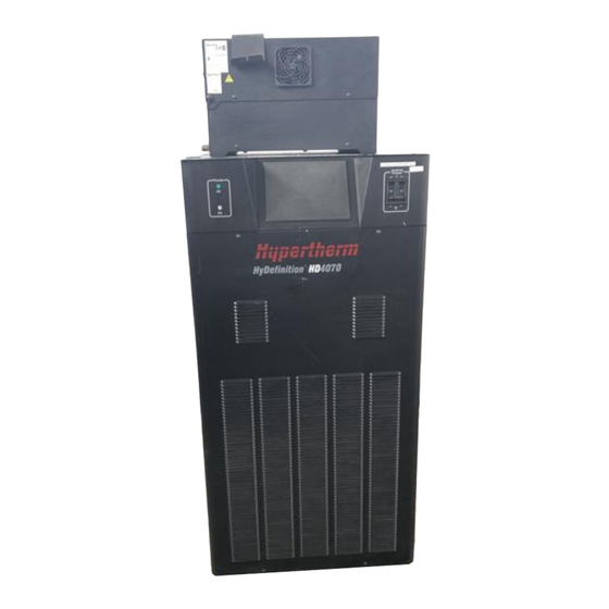
HD4070
Power Supply Display Removal
Remote Installation Kit
Kit Part Numbers
Field Service Bulletin
Revision 1 - December 2000
Hypertherm, Inc.
Hanover, NH USA
www.hypertherm.com
© Copyright 2000 Hypertherm, Inc.
Hypertherm and Command THC are trademarks of Hypertherm, Inc. and may be
registered in the United States and/or other countries.
And
128535
128540
128536
128541
128537
128542
128538
128543
128539
(P/N 803730)
All Rights Reserved
Advertisement
Table of Contents

Related Manuals for Hypertherm HD4070


Summary of Contents for Hypertherm HD4070
- Page 1 (P/N 803730) Revision 1 - December 2000 Hypertherm, Inc. Hanover, NH USA www.hypertherm.com © Copyright 2000 Hypertherm, Inc. All Rights Reserved Hypertherm and Command THC are trademarks of Hypertherm, Inc. and may be registered in the United States and/or other countries.
- Page 2 63457 Hanau-Wolfgang, Deutschland 49 6181 58 2100 Tel 49 6181 58 2134 Fax 49 6181 58 2123 (Technical Service) Hypertherm Singapore Pte Ltd No. 19 Kaki Bukit Road 2 K.B. Warehouse Complex Singapore 417847, Republic of Singapore 65 841 2489 Tel...
- Page 3 This kit provides parts and instructions to remove the display from the power supply and mount it remotely. NOTE: The HD4070 system can only support one touch screen display, either local or remote. Installing displays at both locations on one system may cause malfunctions or damage.
- Page 4 OFF (O). In the U.S., use a "lock-out / tag-out" procedure until the service or maintenance work is complete. In other countries, follow appropriate national or local safety procedures. All work must be performed by a Hypertherm Distributor or a qualified technician. Procedure 1. Turn off the power to the power supply.
- Page 5 HD4070 Display - Remote Installation Kit Remove the cable from the J16 connector on the breakout PC board as shown below. Reposition the jumper blocks on the J23 and J24 connectors on the breakout PC board as shown below. WARNING STATIC ELECTRICITY CAN DAMAGE CIRCUIT BOARDS •...
- Page 6 HD4070 Display - Remote Installation Kit Remove and discard the display cable from the power supply. 4070.60 Install the panel into the power supply as shown below. Install the top panel onto the power supply. 001736 Panel 075250 Screws (4)
- Page 7 HD4070 Display - Remote Installation Kit Mount the remote display as shown below. Mounting Panel (Customer Supplied) 1.7"/43 mm Cutout 5.71"/145 mm 7.835"/199 mm 4070.55 Display - Remote Installation Kit Instructions Page 5...
- Page 8 HD4070 Display - Remote Installation Kit Install the remote display cable to the HD4070 Installation Notes: power supply 1X4 connector and to the display connector as shown below. Mark the identification num- ber on the end of the cable. 10 Install the grounding cable as shown below and...
Need help?
Do you have a question about the HD4070 and is the answer not in the manual?
Questions and answers