Sign In
Upload
Manuals
Brands
Hydreka Manuals
Power Supply
HYDRINS 2
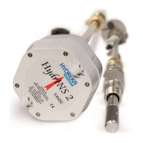
Hydreka HYDRINS 2 Flowmeter Manuals
Manuals and User Guides for Hydreka HYDRINS 2 Flowmeter. We have
4
Hydreka HYDRINS 2 Flowmeter manuals available for free PDF download: Installation Manual, Programming Manual, Manual
Hydreka HYDRINS 2 Programming Manual (77 pages)
electromagnetic insertion flow meters
Brand:
Hydreka
| Category:
Measuring Instruments
| Size: 3 MB
Table of Contents
Hydrins 2 and Hydrins 2 Mini Electromagnetic Insertion Flow Meters Programming of Data Logging
2
Table of Contents
2
1 Introduction
6
2 Basic Programming of Hydrins 2 / Hydrins 2 Mini Flow Meters
6
Figure 1: General Configuration of Winfluid - Situation of the Parameters Menu on the Home Screen
6
Configuration of the Digital Channel of the Hydrins 2 Probe
7
Figure 2: View of the Winfluid Home Screen
7
General Tab
7
Figure 3: Overview of the Sensor Tab
8
Sensor Tab
8
Figure 4: Programming Window for the Hydrins 2 Probe
9
Figure 5: Overview of the Hydrins 2 Probe Programming Window - General Tab
9
General Tab
9
Figure 6: Overview of the Hydrins 2 Probe Programming Window - General Tab - Maximum Allowable Flow Rate to be Observed
10
Display Tab
11
Strategy and Other Tabs
11
Transmission of the Programming
11
Direct Transmission of the Programming to the Hydrins 2 / Hydrins 2 Mini Flow Meter
11
Figure 7: Overview of the Hydrins 2 Probe Programming Window
11
Figure 8: Connection of the CC_HYDA3 or CC_HYDA3S Cable to the Flow Meter
12
Figure 9: Connection Dialogues for Programming
12
Figure 10: Correct Programming Confirmation Dialogues
13
Transmission of the Programming to the Flow Meter During Programming of the Associated Standalone Data Logger
13
Figure 11: Programming Dialogue
14
Figure 12: Connection Dialogues for Flow Meter Programming
14
Figure 13: Correct Programming Confirmation Dialogues
14
Figure 14: Connection Dialogue for Programming
15
Figure 15: Preview Window before Launching Acquisition by the Data Logger
15
Real-Time Reading
16
Taking a Reading of Recorded Data
16
Figure 16: Status Acquisition Window
16
3 Retrieval / Programming of the Flow Meter
17
Retrieval of the Programming to the Hydrins 2 / Hydrins 2 Mini Flow Meter
17
Figure 17: Retrieval of the Flow Meter Programming from the Main Winfluid Screen
17
Programming of a Hydrins 2 / Hydrins 2 Mini Flow Meter
18
Figure 18: Retrieval of the Flow Meter Programming from the Main Winfluid Screen
18
Figure 19: Programming the Flow Meter from the Main Winfluid Screen
18
4 Advanced Programming of the Hydrins2 Probe
19
Programming of Hydrins 2 and Hydrins 2 Mini Flow Meters in Advanced Mode
19
Figure 20: Programming the Flow Meter from the Main Winfluid Screen
19
Conversion Tab
20
Figure 21: Position of the Advanced Button in the Flow Meter Programming Window
20
Figure 22: Password Input Window
20
Figure 23: Advanced Mode - Conversion Tab
20
Figure 24: Flow Signal Saturation Warning Window
21
Calculation Tab
22
Figure 25: Advanced Mode - Sampling Tab
22
Figure 26: Advanced Mode - Calculation Tab
22
Sampling Tab
22
Figure 27: Advanced Mode - 4-20 Ma Tab
23
Ma Tab
23
Figure 28: Advanced Mode - Maintenance Tab
24
Maintenance Tab
24
Instrument Tab
25
Real-Time Monitoring of Recording (to Pre-Locate Leaks by Operating the Step-Test Valves, for Example)
25
Figure 29: Advanced Mode - Instrument Tab
25
Figure 30: Selecting the Computer as Data Logger
26
Configuration
27
Figure 31: Winfluid Home Screen with the Computer as Data Logger
27
Figure 32: Real-Time Display in Computer Mode
28
Use of the Enabled 4-20 Ma Outputs (Display C)
29
Figure 33: Flow Curve
29
Figure 34: Enabling the 4-20 Ma Output of the Display During Programming
30
Figure 35: Display C 4-20 Ma Output Calibration Icon
30
Figure 36: Display C 4-20 Ma Output Calibration Icon
31
Figure 37: Checking the 4-20 Ma Output Using an Ammeter
31
Calculating a Velocity Profile Using the Hydrins 2 / Hydrins 2 Mini Probe
32
Figure 38: Velocity Profile - Maximum Velocities for the Creation of a Velocity Profile
32
Introduction
32
Configuration
33
Figure 39: Launching the Velocity Profile Program from Advanced Mode
33
Figure 40: Launching the Velocity Profile Program from the Winfluid Home Screen
33
Launching the Velocity Profile Program
33
Figure 41: Velocity Profile Editing Window
34
Figure 42: Velocity Profile Editing Window
34
Figure 43: Velocity Profile Measurement Window
35
Measurement
35
Figure 44: Connection of the CC_HYDA3 or CC_HYDA3S Cable to the Flow Meter
36
Figure 45: Probe Routing for the Velocity Profile Measurement
36
Figure 46: Velocity Profile Measurement Window
37
Measurement Procedure
39
Figure 47: Measuring of Probe Raising for the Creation of a Velocity Profile
40
Figure 48: Measurement Point Confirmation Window
41
Processing a Profile
43
Figure 49: Velocity Profile Preview Screen
43
Opening a Velocity Profile
43
Copying a Profile File
44
Deleting a Profile File
44
Figure 50: Measurement Opening Window
44
Figure 51: Selection Window for Measurements to be Copied
44
Figure 52: Copy Destination Directory Selection Window
45
Modifying a Velocity Profile File
45
Printing and Exporting Data from a Velocity Profile
45
Figure 53: Velocity Profile Measurement Export Window
46
Programming a Profile Previously Saved
46
Figure 54: Flow Meter Programming Window with Velocity Profile
47
Figure 55: Programming the Velocity Profile
47
Transferring a Velocity Profile to Winfluid
47
Figure 56: Sending the Velocity Profile Programming to Winfluid
48
Figure 57: Window to Send Coefficients to Winfluid
48
Synchronisation of Pc/Pocket PC Profile Files
49
5 Hydrins Display Software
49
Figure 58: Pocket PC to PC Synchronisation Window
49
Figure 59: Access to the Hydrins Display Management Window
50
Figure 60: Hydrins Display Tool - Access to Configuration
50
Figure 61: Hydrins Display Tool - Configuration
51
Figure 62: Hydrins Display Tool - Display Configuration
51
Figure 63: Hydrins Display Tool - Connection
52
Figure 64: Hydrins Display Tool - Real-Time Display
52
6 Remote Assistance
53
Figure 65: Hydrins Display Tool - Reset Totalisers
53
Figure 66: Hydrins Display Tool - Reset Totalisers - Confirmation
53
Figure 67: Launching Remote Assistance
54
Figure 68: Connection Information for Remote Assistance
54
7 Maintenance
55
Figure 69: Checking the Current Version of Winfluid on the Home Screen
55
Figure 70: Displaying the about Winfluid Section
56
Figure 71: Updating Winfluid from the Main Screen
56
8 Hydrins Software
57
Figure 72: Winfluid Update - Selecting the Update Frequency
57
Figure 73: Winfluid Update - Displaying the Update Information
57
Configuration
58
Figure 74: Hydrins Software - Hydrins Software Home Screen
58
Content of Menus
59
Figure 75: Hydrins Software - Configuration of the Workspace
59
Figure 76: Hydrins Software - List of Tasks Available in the 'Sensor' Menu
59
Sensor Menu
59
Figure 77: Hydrins Software - List of Tasks Available in the 'File' Menu
60
Figure 78: Hydrins Software - File Opening Window
60
Figure 79: Hydrins Software - File Saving Window
60
File Menu
60
Figure 80: Hydrins - Software List of Tasks Available in the 'Maintenance' Menu
61
Figure 81: Serial Output Test Window
61
Maintenance Menu
61
Figure 82: Hydrins Software - Battery Level Display Window
62
Figure 83: Hydrins Software - 4-20 Ma Output Calibration Window
62
Information Displayed
63
Figure 84: Hydrins Software - Output Value Simulation Window
63
Figure 85: Hydrins Software - Hydrins Software Home Window
63
Identification Box
63
Installation Box
64
Sampling Box
64
Units Box
64
Calculation Box
65
Calibration Box
65
Serial Output Tab
65
Figure 86: Hydrins Software - Serial Output Tab Window
66
Display Tab
67
Figure 87: Hydrins Software - 4-20 Ma Programming Window
67
Ma Output Tab
67
Figure 88: Hydrins Software - Display Configuration Window
68
Appendix 1: Velocity Profile Printing Template
69
Appendix 1: Associated Hydreka Catalogue Numbers
70
Table of Illustrations
71
Advertisement
Hydreka HYDRINS 2 Installation Manual (73 pages)
Electromagnetic Insertion Flow Meters
Brand:
Hydreka
| Category:
Measuring Instruments
| Size: 2 MB
Table of Contents
Table of Contents
2
Introduction
6
Measurement Principle
7
Figure 1: Location of Sensor on the Hydrins2/Hydrins 2 Mini Flow Meter
7
Environmental and Safety Conditions
8
Conditions in the Measurement Environment
8
Figure 2: Hydrins 2/Hydrins 2 Mini Data Processing System
8
Software Environment
9
Safety
9
Product Transport
10
Figure 3: Safety Chain
10
Figure 4: Typical Packaging of the Hydrins2/Hydrins 2 Mini
10
Figure 5: Pelicase Transport Case
11
Figure 7: Flow Meter Protection Plug
12
Conditioning the Product before Use
12
Figure 6: Hydrins 2 / Hydrins 2 Mini Guide Bar Connected to the Flow Meter in the Packaging
12
Product Guarantee
12
Description of the Hydrins2/Hydrins 2 Mini Product Range
13
Mechanical Description
13
Figure 8: Mechanical Description of the Hydrins 2 / Hydrins 2 Mini Flow Meter
13
Figure 9: Drawing of the Hydrins 2 and Hydrins 2 Mini Probes
14
Models in the Hydrins 2 / Hydrins 2 Mini Flow Meter Range
15
Installation Location of the Hydrins 2 / Hydrins 2 Mini Flow Meter
17
Choice of Installation Location and Installation and Flow Conditions
17
Figure 10: Flow Conditions to be Observed
17
Velocity Limits for Measurement
18
Figure 11: Maximum Velocity for Different Pipe Internal Diameters
18
Table 1: Upstream Disturbance-Free Straight Lengths to be Observed
18
Figure 13: Valid Positions of the Hydrins2/Hydrins 2 Mini Flow Meter Sensor for Flow Measurement
19
Figure 12: Orders of Magnitude of Maximum Velocities Not to be Exceeded to Create a Velocity Profile
19
Choice of Position for the Electromagnetic Sensor
19
Figure 14: Diagram for the Adaptation of Different Threads for the Installation of the Hydrins 2/Hydrins 2 Mini Flow Meter
20
Valve Diagram for the Installation of Hydrins 2 / Hydrins 2 Mini Flow Meters
20
Inside Diameter Measurement Gauges
21
Figure 15: View of the Different Components of the Diameter Gauge
21
Figure 16: Gauge Pressure Evacuator
22
Installation of the Hydrins 2 / Hydrins 2 Mini Flow Meter
23
Method for Installation at the Centre
23
Step 1/3: Measuring the Inside Diameter ID Using the Gauge
24
Step 2/3: Measurement of Insertion Length at the Centre LI 1/2
25
Step 3/3: Insertion of the Probe
26
Method for Installation at 1/8
27
Figure 17: Diagram of Installation at 1/8 Diameter
27
Table 2: Correspondence of Lengths L with the Hydrins Probe Model for an Installation at
27
Figure 19: Aligning the Flow Meter in the Direction of Flow
28
Aligning the Guide Bar with the Direction of Flow
28
Figure 18: Position of the Positive Direction Arrow on the Probe Head
28
Installing the Pressure Channel on a Data Logger
29
Processing of Data Measured by Display or Recording
29
Figure 20: Quickfit Connector for the Pressure Channel between Data Logger and Probe
29
Installation of a Display a or a Display C
31
Overview of Displays a and C
31
Figure 21: Installation Configurations for Hydrins 2/Hydrins 2 Mini
31
Figure 22: Inputs and Outputs of Displays a and C
32
Table 3: Outputs of Displays a and C
32
Wall Mounting of Display a or Display C
33
Figure 23: Application of the Magnet to the Magnetic Switch to Activate the Display
33
Figure 24: Layout Diagram for the Wall Mounting of a Display a or C
33
Figure 25: Remove the Screws from the Head of the Hydrins 2 Flow Meter
34
Equipment
34
Removal
34
Mode Change of the Hydrins 2 and Hydrins 2 Mini Probes
34
Figure 26: Overview of the Inside of the Hydrins 2 Flow Meter Head
35
Figure 27: Removal of the Head of the Hydrins 2 Flow Meter from the Compartment
35
Mode Change
36
Electrical Power Supply of Display a
36
Figure 28: Mode 1/Mode 2 Change and Arrangement of Batteries in the Hydrins 2 Flow Meter
36
Figure 29: Locating Guides for the Head of the Hydrins 2 Flow Meter
36
Internal Power Supply Using 3.6 VDC Lithium Batteries
37
Figure 30: Positions of Connector J15 and Switch SW2 Inside Display a
37
External Power Supply Using 3.6 VDC Lithium Batteries
38
Figure 31: Connection of the Lithium Battery
38
Figure 32: Position to Use for an External 3.6 V Power Supply
38
Figure 33: Position to Use for an External 9-28 V Power Supply
39
External 9 to 28 VDC Power Supply Connected to the Internal Terminals
39
Internal Power Supply Using Alkaline Batteries
39
Electrical Power Supply of Display C
40
Figure 34: Power Supply of a Display a with CNT 104 or CNT 105
40
External Power Supply by Military Connector
40
Figure 35: Selection of the Type of Power Supply for Display C
41
Figure 36: Power Supply of a Display C with CNT 104 or CNT 105
41
Wiring of the Entities of the Measurement Chain
42
Figure 37: Wiring Possibilities from a Hydrins 2 / Hydrins 2 Mini Flow Meter Without Display
42
Figure 38: Wiring Possibilities from a Hydrins 2 / Hydrins 2 Mini Flow Meter with Display (Mode 2)
43
Figure 39: 4-20 Ma Outputs on Display C
44
Internal Wiring
45
Connections of the Flow Meter Pulse Output to the Display Terminal Block
45
Figure 40: Output Connector Pin Correspondence Diagram
45
Figure 41: Output Connector Pin Correspondence Diagram
45
Table 6: Pulse Output Connections - Terminal Block Designation - Output
46
Pulse Output Connections to the Display Terminal Block
46
Figure 42: Location of Pulse Outputs
46
Table 5: Cable Connections According to Their Colour and Terminal Designation
46
Wiring the 4-20 Ma Outputs to the Terminal Block of Display C
47
Figure 43: Connection of Pulse Outputs to Terminal Block
47
Figure 44: Location of the 4-20 Ma Outputs (Display C)
47
Table 7: Connections for the Active 4 - 20 Ma Outputs (Power Supplied by the Display Unit)
47
Protecting the Displays from Lightning and Surges
48
Figure 45: Connection of the Pulse Outputs to the Terminal Block of Display C
48
Maintenance
49
Figure 46: Lightning Protection of Display C
49
Figure 47: Maintenance of a Flow Meter Measuring Water Loaded with Metal Particles
50
Figure 48: Hydraulic Bench for the Calibration of Hydrins 2/ Hydrins 2 Mini Flow Meters and HYDREKA Calibration Certificate
50
Calibration
50
Maintenance
50
Replacing the Batteries of the Hydrins 2 / Hydrins 2 Mini Flow Meter
51
Replacing the Batteries in Display a
51
Figure 49: Reinitialisation of the Battery Levels in Hydrins 2 in Mode 1 in Winfluid
51
In Winfluid
51
Product Disposal
52
Figure 50: Reinitialisation of Battery Levels in Hydrins 2 / Hydrins 2 Mini in Mode 2 with a Display a
52
Appendix 1: Selection Guide - the Right Hydrins 2 Model for Your Measurement Site According to Your Pipe
53
Appendix 2: Inside Diameter Gauges
62
Hydrins 2 Mini Products
63
Appendix 4: Template for Hydreka Calibration Certificate for the Hydrins
67
Hydrins 2 Mini Flow Meter
67
Table of Illustrations
68
List of Tables
70
Hydreka HYDRINS 2 Installation Manual (79 pages)
Electromagnetic Insertion Flow Meters
Brand:
Hydreka
| Category:
Measuring Instruments
| Size: 2 MB
Table of Contents
Table of Contents
2
1 Safety Instructions
6
2 Introduction
8
Measurement Principle
9
Figure 1: Location of the Sensor on the Hydrins2/Hydrins 2 Mini Flow Meter
9
Environmental and Safety Conditions
10
Conditions in the Measurement Environment
10
Figure 2: Hydrins 2/Hydrins 2 Mini Data Processing System
10
Safety
11
Product Transport
12
Figure 3: Safety Chain
12
Figure 4: Typical Packaging of the Hydrins2/Hydrins 2 Mini
12
Figure 5: Pelicase Transport Case
13
Product Guarantee
14
Conditioning the Product before Use
14
Figure 6: Hydrins 2 / Hydrins 2 Mini Guide Bar Connected to the Flow Meter in the Packaging
14
Figure 7: Flow Meter Protection Plug
14
3 Description of the Hydrins2/Hydrins 2 Mini Product Range
15
Mechanical Description
15
Figure 8: Mechanical Description of the Hydrins 2 / Hydrins 2 Mini Flow Meter
15
Figure 9: Drawing of Hydrins 2 and Hydrins 2 Mini Probes
16
Models in the Hydrins 2 / Hydrins 2 Mini Flow Meter Range
17
4 Installation Location of the Hydrins 2 / Hydrins 2 Mini Flow Meter
19
Choice of Installation Location and Installation and Flow Conditions
19
Figure 10: Flow Conditions to be Observed
19
Velocity Limits for Measurement
20
Figure 11: Maximum Velocity for Different Pipe Internal Diameters
20
Table 1: Upstream Disturbance-Free Straight Lengths to be Observed
20
Choice of Position for the Electromagnetic Sensor
21
Figure 12: Orders of Magnitude of Maximum Velocities Not to be Exceeded to Create a Velocity Profile
21
Typical Installation of Hydrins 2 / Hydrins 2 Mini Flow Meters
22
Figure 13: Valid Positions of the Hydrins 2/Hydrins 2 Mini Flow Meter Sensor for Flow Measurement
22
Inside Diameter Measurement Gauges
23
Figure 14: View of the Different Components of the Diameter Gauge
23
Figure 15: Gauge Pressure Evacuator
23
5 Installation of the Hydrins 2 / Hydrins 2 Mini Flow Meter
24
Method for Installation at the Centre
24
Step 1/3: Measuring the Inside Diameter DI Using the Gauge
25
Step 2/3: Measure Length of Insertion at the Centre LI 1/2
26
Step 3/3: Probe Insertion
27
Method for Installation at 1/8
28
Figure 16: Diagram of Installation at 1/8 Diameter
28
Table 2: Correspondence of Lengths L with the Hydrins Probe Model for an Installation at 1/8Th Diameter
28
Aligning the Guide Bar with the Direction of Flow
29
Figure 17: Position of the Positive Direction Arrow on the Probe Head
29
Figure 18: Aligning the Flow Meter in the Direction of Flow
29
6 Installing the Pressure Channel on a Data Recorder
30
Figure 19: Quickfit Connector for the Pressure Channel between Recorder and Probe
30
7 Viewing Measurements by Display or Recording
31
8 Installation of a Display
32
Preview of Displays
32
Figure 20: Installation Configurations for Hydrins 2 / Hydrins 2 Mini
32
Mounting the Display Unit on a Wall
33
Figure 21: Application of the Magnet to the Magnetic Switch to Activate the Display
33
Figure 22: Dimensions for Wall-Mounting a Display
33
Mode Change of the Hydrins 2 and Hydrins 2 Mini Probes
34
Equipment
34
Removal
34
Figure 23: Remove the Screws from the Head of the Hydrins 2 Flow Meter
34
Figure 24: Overview of the Inside of the Hydrins 2 Flow Meter Head
35
Mode Change
36
Figure 25: Removal of the Cover from the Head of the Hydrins 2 Flow Meter
36
Figure 26: Mode 1/Mode 2 Change and Arrangement of Batteries in the Hydrins 2 Flow Meter
37
Figure 27: Locating Guides for the Head of the Hydrins 2 Flow Meter
37
Electrical Power Supply of Display a
39
Figure 28: Positions of Connector J15 and Switch SW2 Inside Display a
40
Internal Power Supply Using 3.6 VDC Lithium Batteries
41
External Power Supply Using 3.6 VDC Lithium Batteries
41
Figure 29: Connection of the Lithium Battery
41
Figure 30: Position to Use for an External 3.6 V Power Supply
41
Internal Power Supply Using Alkaline Batteries
42
External 9 to 28 VDC Power Supply Connected to the Internal Terminals
42
Figure 31: Position to Use for an External 9-28 V Power Supply
42
External Power Supply by Military Connector
43
Electrical Power Supply of Display C
43
Electrical Power Supply of Display and Recording Unit
44
Figure 32: Selection of the Type of Power Supply for Display C
44
Wiring of the Entities of the Measurement Chain
45
Figure 33: Wiring Possibilities from a Hydrins 2/Hydrins 2 Mini Flow Meter Without Display (Mode 1)
45
Table 3: Wiring of Hydrins 2 / Hydrins 2 Outputs in Mode 1
45
Figure 34: Wiring Possibilities from a Hydrins 2 / Hydrins 2 Mini Flow Meter with Display (Mode 2)
46
Figure 35: 4-20 Ma Outputs on Display C
47
Internal Wiring
48
Connections of the Hydrins Probe to the Display Terminal Block
48
Figure 36: Diagram: Connecting the Hydrins Probe to the Display
48
Pulse Output Connections to the Display Terminal Block
49
Figure 37: Location of Pulse Outputs
49
Table 4: Cable Connections According to Colour and Terminal Block Designation
49
Wiring the 4-20 Ma Outputs to the Terminal Block of Display C
50
Figure 38: Location of the 4-20 Ma Outputs (Display C)
50
Table 5: Connection of Pulse Outputs - Terminal Block Designation - Output
50
Table 6: Connections for the Active 4 - 20 Ma Outputs (Power Supplied by the Display Unit)
51
9 Technical Characteristics
53
Hydrins II Probe
53
Display Units
54
10 Maintenance
55
Figure 39: Maintenance of a Flow Meter Measuring Water Loaded with Metal Particles
55
Calibration
56
Figure 40: Hydraulic Bench for the Calibration of Hydrins 2 / Hydrins 2 Mini Flow Meters and HYDREKA Calibration Certificate
56
Replacing the Batteries of the Hydrins 2 / Hydrins 2 Mini Flow Meter
57
Replacing the Display Batteries
57
Figure 41: Reinitialisation of the Battery Levels in Hydrins 2 in Mode 1 in Winfluid
57
12 Product Disposal
58
Figure 42: Reinitialisation of Battery Levels in Hydrins 2 / Hydrins 2 Mini in Mode 2 with a Display a
58
Appendix 1: Selection Guide: the Right Hydrins 2 Model for Your Measurement Site According to Your Pipe
59
Appendix 2: Inside Diameter Gauges
68
Hydrins 2 Products
69
Appendix 4: Template for Hydreka Calibration Certificate for the Hydrins
73
Hydrins 2 Mini Flow Meter
73
Table of Illustrations
74
List of Tables
76
Advertisement
Hydreka HYDRINS 2 Manual (12 pages)
CHANGES OF MODE AND POWER SUPPLY AND ITS DISPLAY
Brand:
Hydreka
| Category:
Power Supply
| Size: 5 MB
Table of Contents
Table of Contents
2
1 I ) Hydrins 2 : Change of Mode (with or Without Display)
3
Tools
3
Disassembling
3
Change of MODE
5
Reassembling
6
2 Display : Lithium Batteries to External Power Supply
6
II.1 ) External Power Supply with Internal Connection (6-28V)
7
II.1.A ) Configuration of Switches SW1, SW2 Et
7
Sw3
7
II.2 ) External Power Supply with the Military Connector (6-28V)
9
II.2.A ) Configuration of Switches SW1, SW2 Et
9
Sw3
9
3 Display : External Power Supply to Lithium Batteries
10
III.1 ) Configuration of Switches SW1, SW2 Et
10
Sw3
10
4 DISPLAY : EXTERNAL POWER SUPPLY for 4-20 Ma OUTPUT to
11
Lithium Batteries for Pulse
11
IV.1 ) Disable the 4-20 Ma Function
11
Display : External Power Supply for 4-20 Ma Output to Lithium Batteries for Pulse Output
11
Sw3
12
Advertisement
Related Products
Hydreka HydrINS 2 Mini
Hydreka Categories
Measuring Instruments
Power Supply
More Hydreka Manuals
Login
Sign In
OR
Sign in with Facebook
Sign in with Google
Upload manual
Upload from disk
Upload from URL