Hydreka HydrINS 2 Installation Manual
Electromagnetic insertion flow meters
Hide thumbs
Also See for HydrINS 2:
- Manual (12 pages) ,
- Programming manual (77 pages) ,
- Installation manual (79 pages)
Table of Contents
Advertisement
Quick Links
Advertisement
Chapters
Table of Contents

Related Manuals for Hydreka HydrINS 2


Summary of Contents for Hydreka HydrINS 2
- Page 1 HydrINS 2 / HydrINS 2 Mini Flow Meter Page 1/73 Installation Manual HydrINS 2 and HydrINS 2 Mini Electromagnetic Insertion Flow Meters Installation Manual Revision Date Author Modifications Signature 15/02/11 Approval 15/12/10 Updated...
-
Page 2: Table Of Contents
Velocity limits for measurement ..................18 Choice of position for the electromagnetic sensor ............. 19 Valve diagram for the installation of HydrINS 2 / HydrINS 2 Mini flow meters ....20 Inside diameter measurement gauges ................21 INSTALLATION OF THE HYDRINS 2 / HYDRINS 2 MINI FLOW METER ......23 Method for installation at the centre: ................ - Page 3 INSTALLATION OF A DISPLAY A OR A DISPLAY C ............31 Overview of Displays A and C .................... 31 Wall mounting of Display A or Display C ................33 Mode change of the HydrINS 2 and HydrINS 2 Mini probes ..........34 7.3.1 Equipment ........................... 34 7.3.2...
- Page 4 MAINTENANCE ......................49 MAINTENANCE ......................50 Calibration ........................50 Replacing the batteries of the HydrINS 2 / HydrINS 2 Mini flow meter ....... 51 Replacing the batteries in Display A .................. 51 PRODUCT DISPOSAL ....................52 APPENDIX 1: SELECTION GUIDE - THE RIGHT HYDRINS 2 MODEL FOR YOUR MEASUREMENT SITE ACCORDING TO YOUR PIPE ..................
- Page 5 2/HydrINS 2 Mini in the configuration with Displays A and C For acquisition programming, refer to the HydrINS 2 / HydrINS 2 Mini flow meter programming manual, the programming manual for the data logger used, and the programming manual for an...
-
Page 6: Introduction
The position at one eighth of the diameter, a position representing the average speed The velocity sensor of the HydrINS 2/HydrINS 2 Mini flow meter can be inserted in different positions across the cross-section of the pipe. This allows a flow velocity profile to be created in order to refine the mean speed calculation and therefore also the flow measurement. -
Page 7: Measurement Principle
In the case of HydrINS 2/HydrINS 2 Mini, the magnetic field is generated by a coil at the end of the probe, and the water passing through the pipe, whose conductivity must be at least 20 µS/cm, represents the conductor. -
Page 8: Environmental And Safety Conditions
Figure 2: HydrINS 2/HydrINS 2 Mini data processing system 1.2 Environmental and safety conditions Optimum use of the HydrINS 2 flow meter requires a suitable measurement environment in order to avoid as far as possible any environmental disturbances that could affect the measurement. -
Page 9: Software Environment
MUST BE GREATER THAN 20µS/cm. 1.4 Software environment The HydrINS 2 and HydrINS 2 Mini and Displays A and C are configurable using Winfluid and Winfluid Mobile software, developed by Hydreka. Minimum software version: Winfluid 2.98 or Winfluid Mobile 1.98 1.5 Safety... -
Page 10: Product Transport
It is connected to a hook that can pivot around the probe. 1.6 Product transport The HydrINS 2 / HydrINS 2 Mini flow meters are delivered in an appropriate box with polystyrene blocks to protect them during transport. Figure 4: Typical packaging of the HydrINS2/HydrINS 2 Mini... -
Page 11: Figure 5: Pelicase Transport Case
HydrINS 2 / HydrINS 2 Mini Flow Meter Page 11/73 Installation Manual Reinforced cases, called PELICASE, are also available for the transport of HydrINS 2/HydrINS 2 Mini 300 to 700 models and their accessories: Figure 5: Pelicase transport case Your package, whether a box or a case, must contain:... -
Page 12: Product Guarantee
Contact Hydreka Customer Service to invoke this guarantee if necessary. 1.8 Conditioning the product before use The sensor of the HydrINS 2/HydrINS 2 Mini flow meter must be soaked for one day before use in order to obtain stable measurements. -
Page 13: Description Of The Hydrins2/Hydrins 2 Mini Product Range
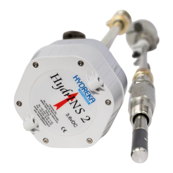
2 Description of the HydrINS2/HydrINS 2 Mini product range 2.1 Mechanical description: Alignment stem Probe head with orientation arrow Communication port and pulse output Insertion marking Clamp ring Pressure output Sensor Figure 8: Mechanical description of the HydrINS 2 / HydrINS 2 Mini flow meter... -
Page 14: Figure 9: Drawing Of The Hydrins 2 And Hydrins 2 Mini Probes
*A: dimension A is 689 for Cat. No.:SI_HYDA2P-30 / 869 for Cat. No. SI_HYDA2P-50 / 1109 for SI_HYDA2P-70 / 1409 for SI_HYDA2P-100 / 500 for Cat. No. SI_HYDE2-15 Figure 9: Drawing of the HydrINS 2 and HydrINS 2 Mini probes... -
Page 15: Models In The Hydrins 2 / Hydrins 2 Mini Flow Meter Range
2.2 Models in the HydrINS 2 / HydrINS 2 Mini flow meter range The following table is a selection guide to identify the most appropriate HydrINS 2 model according to the pipe diameter and dimensions as shown in the diagram above: ... - Page 16 Min. Table 7: Clearance heights above the insertion point required for installation of a HydrINS 2 / HydrINS 2 Mini flow meter. Appendix 1 presents the HydrINS 2 / HydrINS 2 Mini flow meter models that can be used for several...
-
Page 17: Installation Location Of The Hydrins 2 / Hydrins 2 Mini Flow Meter
Page 17/73 Installation Manual 3 Installation location of the HydrINS 2 / HydrINS 2 Mini flow meter 3.1 Choice of installation location and installation and flow conditions For accurate measurement of the flow, the pipe must be continuously carrying a flow, and disturbance-free upstream and downstream distances ('straight lengths') must be observed. -
Page 18: Velocity Limits For Measurement
The creation of a velocity profile is used to refine the insertion factor and profile factor values (refer to the HydrINS 2 / HydrINS 2 Mini flow meter acquisition programming manual). The order of magnitude of the maximum velocities to be observed are indicated on the chart below. -
Page 19: Choice Of Position For The Electromagnetic Sensor
At the centre of the pipe At 1/8th of the pipe diameter Position at 1/8 diameter, mean velocity Position at 1/2 diameter, mean velocity Figure 13: Valid positions of the HydrINS2/HydrINS 2 Mini flow meter sensor for flow measurement... -
Page 20: Valve Diagram For The Installation Of Hydrins 2 / Hydrins 2 Mini Flow Meters
7 - ф 25 mm or ф 19 mm (HydrINS 2 Mini) pipe drilling BALL VALVE PIPE TO BE EQUIPPED WITH INSTRUMENTATION INSERT COLLAR Figure 14: Diagram for the adaptation of different threads for the installation of the HydrINS 2/HydrINS 2 Mini flow meter... -
Page 21: Inside Diameter Measurement Gauges
3/4" insert – drill 19 mm at least: this does not require an adapter. The preparation of an insertion point compatible with HydrINS 2 or HydrINS 2 Mini is exactly the same as for the preparation of a classic insertion point for the installation of a connection. No additional accessories are required. -
Page 22: Figure 16: Gauge Pressure Evacuator
HydrINS 2 / HydrINS 2 Mini Flow Meter Page 22/73 Installation Manual Figure 16: Gauge pressure evacuator Note that a gauge can be created with a personalised size and thread (please ask us). Available gauge models and their sizes are described in detail in Appendix 2... -
Page 23: Installation Of The Hydrins 2 / Hydrins 2 Mini Flow Meter
HydrINS 2 / HydrINS 2 Mini Flow Meter Page 23/73 Installation Manual 4 Installation of the HydrINS 2 / HydrINS 2 Mini flow meter 4.1 Method for installation at the centre: The method for installing the probe at the centre, described below, includes three stages: 1. -
Page 24: Step 1/3: Measuring The Inside Diameter Id Using The Gauge
HydrINS 2 / HydrINS 2 Mini Flow Page 24/73 Meter User Manual 4.1.1 Step 1/3: Measuring the inside diameter ID using the gauge. Freely rotating ring Immobilised ring Ring A Ring B Tighten the diameter gauge, 1. Open the insert valve and lower 1. -
Page 25: Step 2/3: Measurement Of Insertion Length At The Centre Li 1/2
HydrINS 2 / HydrINS 2 Mini Flow Page 25/73 Meter User Manual 4.1.2 Step 2/3: Measurement of insertion length at the centre 1. From the last position, 1. Raise the gauge fully. 1. Tighten Ring B. place Ring A half-way along 2. -
Page 26: Step 3/3: Insertion Of The Probe
HydrINS 2 / HydrINS 2 Mini Flow Page 26/73 Meter User Manual 4.1.3 Step 3/3: Insertion of the probe Installation at the centre 1. Close the insertion valve, tighten the probe, and lower the probe until it stops on the ball of the valve. -
Page 27: Method For Installation At 1/8
HydrINS 2 / HydrINS 2 Mini Flow Page 27/73 Meter User Manual 4.2 Method for installation at 1/8 For an installation at 1/8 diameter, the distance Z after probe insertion must be equal to: = L - E - 1/8 ID ... -
Page 28: Aligning The Guide Bar With The Direction Of Flow
The orientation of the HydrINS 2 / HydrINS 2 Mini flow meter must now be adjusted. The head of the HydrINS 2 / HydrINS 2 Mini flow meter has a red arrow to orient the flow meter in the main direction of flow. Flow in this direction will count as positive, whilst flow in the reverse direction will count as negative. -
Page 29: Installing The Pressure Channel On A Data Logger
5 Installing the pressure channel on a data logger The HydrINS 2 / HydrINS 2 Mini insertion flow meter has a Quickfit connector to measure the pressure at the same point as the flow rate measurement. - Page 30 With a Display C: External DC power supply (20-28 volts) with two 4-20 mA outputs (on terminal block) and four pulse outputs (two on terminal block, two on output connector). The HydrINS 2/HydrINS 2 Mini flow meter operates in two separate modes: ...
-
Page 31: Installation Of A Display A Or A Display C
Figure 21: Installation configurations for HydrINS 2/HydrINS 2 Mini It is essential to ensure that the HydrINS 2 / HydrINS 2 Mini flow meter is configured in the appropriate operating mode before placing it in operation; otherwise, the probe will suffer irreversible damage (see paragraph 7.2) -
Page 32: Figure 22: Inputs And Outputs Of Displays A And C
HydrINS 2 / HydrINS 2 Mini Flow Meter Page 32/73 User Manual DISPLAY A OUTPUTS (BLUE) (internal external lithium battery) or 9-28 VDC Cable CNT120S CC_HYDA3S DISPLAY A OUTPUTS communication DISPLAY C OUTPUTS (GREEN) 20-28 VDC CC_HYDA3S CNT120S PC or PDA... -
Page 33: Wall Mounting Of Display A Or Display C
HydrINS 2 / HydrINS 2 Mini Flow Meter Page 33/73 User Manual To reduce energy consumption, the display is activated manually using a magnet included with the Display. This magnet must be applied to a magnetic zone on the side of the Display, the magnetic switch, in order to activate the Display. -
Page 34: Mode Change Of The Hydrins 2 And Hydrins 2 Mini Probes
The change of the probe power supply mode must be performed with care. If not, there is a risk of causing severe electrical damage to the flow meter. 7.3.1 Equipment The following equipment is required to remove the HydrINS 2/HydrINS 2 Mini probe head: Flat head screwdriver ... -
Page 35: Figure 26: Overview Of The Inside Of The Hydrins 2 Flow Meter Head
Figure 26: Overview of the inside of the HydrINS 2 flow meter head Loosen the three flat-head screws securing the battery holder, and remove it. Figure 27: Removal of the head of the HydrINS 2 flow meter from the compartment... -
Page 36: Mode Change
Battery 1 kept connection Figure 28: Mode 1/Mode 2 change and arrangement of batteries in the HydrINS 2 flow meter Reinstall the cover using the alignment guides: Figure 29: Locating guides for the head of the HydrINS 2 flow meter 7.4 Electrical power supply of Display A... -
Page 37: Internal Power Supply Using 3.6 Vdc Lithium Batteries
HydrINS 2 / HydrINS 2 Mini Flow Meter Page 37/73 User Manual Internal 9 to 28 VDC alkaline battery pack An external 9 to 28 VDC power supply connected to the labelled 9-28 VDC terminals A 9 to 28 VDC external power supply connected to the military connector These different power supply modes can be implemented using the two elements illustrated below: ... -
Page 38: External Power Supply Using 3.6 Vdc Lithium Batteries
HydrINS 2 / HydrINS 2 Mini Flow Meter Page 38/73 User Manual Figure 31: Connection of the lithium battery 7.4.2 External power supply using 3.6 VDC lithium batteries 1 – Create the following configuration: Switch SW2: External Connector J15: Connect 1-2 and 15-16 2 –... -
Page 39: Internal Power Supply Using Alkaline Batteries
HydrINS 2 / HydrINS 2 Mini Flow Meter Page 39/73 User Manual 7.4.3 Internal power supply using alkaline batteries 1 – Remove all connections from Connector J15, and then connect the additional board, Cat. No., 4005511 to the same connector. In this case, the position of Switch SW2 used earlier is no longer relevant. -
Page 40: External Power Supply By Military Connector
HydrINS 2 / HydrINS 2 Mini Flow Meter Page 40/73 User Manual 7.4.5 External power supply by military connector For connection to the military connector, use a CNT104/CNT105 cable, and then connect the banana plugs to an external power supply. -
Page 41: Figure 35: Selection Of The Type Of Power Supply For Display C
HydrINS 2 / HydrINS 2 Mini Flow Meter Page 41/73 User Manual Terminal MilSpec Figure 35: Selection of the type of power supply for Display C Figure 36: Power supply of a Display C with CNT 104 or CNT 105... -
Page 42: Wiring Of The Entities Of The Measurement Chain
Octopus LX Remote logger) (SMS/GPRS) manageme Figure 37: Wiring possibilities from a HydrINS 2 / HydrINS 2 Mini flow meter without Display (Mode 1) Receiver Cat. No. of cable used CNT 90S Standalone data logger (Lolog, Vista +, etc.) CNT 102S... -
Page 43: Figure 38: Wiring Possibilities From A Hydrins 2 / Hydrins 2 Mini Flow Meter With Display (Mode 2)
(communicating manageme data logger) loggers (please ask data logger) Figure 38: Wiring possibilities from a HydrINS 2 / HydrINS 2 Mini flow meter with Display (Mode 2) Receiver Cat. No. of cable used CNT 120S Display A (blue) It is also possible to retrieve a pulse output from a Display A on another pulse acquisition system (standalone data logger, SCADA or remote management) by connecting the Display and the acquisition system. -
Page 44: Figure 39: 4-20 Ma Outputs On Display C
HydrINS 2 / HydrINS 2 Mini Flow Meter Page 44/73 User Manual CNT 120S Computer, PDA CC_HYDA3S (200 metres max) Display C (green) 4-20 mA (Bare wires) Remote manageme Figure 39: 4-20 mA outputs on Display C Receiver Cat. No. of cable used... -
Page 45: Internal Wiring
The PIN numbers correspond to the following connector diagram: Figure 40: Output connector pin correspondence diagram Each PIN number corresponds to a coloured wire at the other end of the HydrINS 2/HydrINS 2 Mini connection cable > Display A or C... -
Page 46: Pulse Output Connections To The Display Terminal Block
HydrINS 2 / HydrINS 2 Mini Flow Meter Page 46/73 User Manual Pin No. on Probe Connector Colour Terminal Description Not Connected Screening Screen Purple Com Frq White/Blue Frq Out 1 Black Green RS232 GND White/Yellow Freq Out 2 Blue... -
Page 47: Wiring The 4-20 Ma Outputs To The Terminal Block Of Display C
HydrINS 2 / HydrINS 2 Mini Flow Meter Page 47/73 User Manual Reconnect the connector and retighten the cable gland. Figure 43: Connection of pulse outputs to terminal block If the cable has a braid, it can be connected to the Screen output of the connector in case of electrical interference. -
Page 48: Protecting The Displays From Lightning And Surges
7.8 Protecting the displays from lightning and surges the HydrINS2 / HydrINS 2 Mini insertion flow meter and Displays A and C have no protection against lightning and surges. We recommend the installation of an external device to protect it from surges caused by lightning... -
Page 49: Maintenance
Figure 46: Lightning protection of Display C 8 Maintenance Maintenance of the HydrINS2 / HydrINS 2 Mini product is very easy: simply remove the probe from the insert (ensure that the chain is taut when reassembling). This maintenance procedure is very economical compared to the maintenance of an electromagnetic sleeve, for example. -
Page 50: Maintenance
HYDREKA, which has a COFRAC-connected hydraulic bench for flow meter calibration. Figure 48: Hydraulic bench for the calibration of HydrINS 2/ HydrINS 2 Mini flow meters and HYDREKA calibration certificate A calibration certificate is issued at the end of the calibration phase (see Appendix 4). -
Page 51: Replacing The Batteries Of The Hydrins 2 / Hydrins 2 Mini Flow Meter
User Manual 9.2 Replacing the batteries of the HydrINS 2 / HydrINS 2 Mini flow meter Apply the following procedure to replace the batteries in the head of the HydrINS 2 / HydrINS 2 Mini flow meter: 1 – Open the head of the flow meter 2 –... -
Page 52: Product Disposal
Page 52/73 User Manual Figure 50: Reinitialisation of battery levels in HydrINS 2 / HydrINS 2 Mini in Mode 2 with a Display A in Winfluid 10 Product disposal The product must be disposed of in accordance with local regulations concerning the disposal of... -
Page 53: Appendix 1: Selection Guide - The Right Hydrins 2 Model For Your Measurement Site According To Your Pipe
Appendix 1: Selection Guide - The right HydrINS 2 model for your measurement site according to your pipe The following table shows the compatibility of standardised diameters with the available HydrINS 2 / HydrINS 2 Mini models Steel HydrINS 2 "300"... - Page 54 HydrINS 2 / HydrINS 2 Mini Flow Meter User Page 54/73 Manual Asbestos - Cement HydrINS 2 "300" HydrINS 2 "500" HydrINS 2 "700" HydrINS 2 "1000" HydrINS 2 Mini Inside Type of Velocity Velocity Velocity Velocity Velocity Material diameter...
- Page 55 HydrINS 2 / HydrINS 2 Mini Flow Meter User Page 55/73 Manual HDPE HydrINS 2 "300" HydrINS 2 "500" HydrINS 2 "700" HydrINS 2 "1000" HydrINS 2 Mini Inside Type of Velocity Velocity Velocity Velocity Velocity Material diameter Centre Centre...
- Page 56 HydrINS 2 / HydrINS 2 Mini Flow Meter User Page 56/73 Manual PVC PN 10 HydrINS 2 "300" HydrINS 2 "500" HydrINS 2 "700" HydrINS 2 "1000" HydrINS 2 Mini Inside Type of Velocity Velocity Velocity Velocity Velocity Material diameter...
- Page 57 HydrINS 2 / HydrINS 2 Mini Flow Meter User Page 57/73 Manual PVC PN 16 HydrINS 2 "300" HydrINS 2 "500" HydrINS 2 "700" HydrINS 2 "1000" HydrINS 2 Mini Inside Type of Velocity Velocity Velocity Velocity Velocity Material diameter...
- Page 58 HydrINS 2 / HydrINS 2 Mini Flow Meter User Page 58/73 Manual K9 Ductile Cast Iron HydrINS 2 "300" HydrINS 2 "500" HydrINS 2 "700" HydrINS 2 "1000" HydrINS 2 Mini Inside Type of Velocity Velocity Velocity Velocity Velocity Material...
- Page 59 HydrINS 2 / HydrINS 2 Mini Flow Meter User Page 59/73 Manual C40 Ductile Cast Iron HydrINS 2 "300" HydrINS 2 "500" HydrINS 2 "700" HydrINS 2 "1000" HydrINS 2 Mini Inside Type of Velocity Velocity Velocity Velocity Velocity Material...
- Page 60 HydrINS 2 / HydrINS 2 Mini Flow Meter User Page 60/73 Manual Grey cast iron HydrINS 2 "300" HydrINS 2 "500" HydrINS 2 "700" HydrINS 2 "1000" HydrINS 2 Mini Inside Type of Velocity Velocity Velocity Velocity Velocity Material diameter...
- Page 61 HydrINS 2 / HydrINS 2 Mini Flow Meter User Page 61/73 Manual Bonna Sabla HydrINS 2 "300" HydrINS 2 "500" HydrINS 2 "700" HydrINS 2 "1000" HydrINS 2 Mini Inside Type of Velocity Velocity Velocity Velocity Velocity Material diameter Centre...
-
Page 62: Appendix 2: Inside Diameter Gauges
2" BSP 1250 1450 NPT thread JD_HYD10A-088 1" NPT 1000 JD_HYD10A-1000 1" NPT 1000 1200 JD_HYD10A-125 1" NPT 1250 1450 JD_HYD20A-100 2" NPT 1000 1200 JD_HYD20A-125 2" NPT 1250 1450 Table 7: Descriptive characteristics of diameter gauges marketed by HYDREKA... -
Page 63: Hydrins 2 Mini Products
Numbers associated with the range of HydrINS 2 / HydrINS 2 Mini products HydrINS 2 flow meters HydrINS 2 insertion flow meter - Model 300 - BSP SI_HYDA2P-30 thread HydrINS 2 insertion flow meter - Model 500 - BSP SI_HYDA2P-50... - Page 64 Communication leads HydrINS probe digital output cable - RADCOM CNT102S recorders HydrINS 2 - Display signal output cable, 5 m CNT120S -5 HydrINS 2 - Display signal output cable, 10 m CNT120S- 10 HydrINS 2 digital output cable, two bare wires,...
- Page 65 HydrINS 2 / HydrINS 2 Mini Flow Meter Page 65/73 User Manual Gauges BSP thread 1" BSP gauge - dia. 500 mm max. JD_HYD_10-088 1" BSP gauge - dia. 700 mm max. JD_HYD_10-1000 1" BSP gauge - dia. 900 mm max.
- Page 66 HydrINS 2 / HydrINS 2 Mini Flow Meter Page 66/73 User Manual PELICASE cases Waterproof case (908 x 351 x 133 mm inside) for VALPEL1700 HydrINS 300 Waterproof case (1060 x 343 x 133 mm inside) for VALPEL1720 HydrINS 500...
-
Page 67: Appendix 4: Template For Hydreka Calibration Certificate For The Hydrins
HydrINS 2 / HydrINS 2 Mini Flow Meter Page 67/73 User Manual Appendix 4: Template for HYDREKA calibration certificate for the HydrINS 2 / HydrINS 2 Mini flow meter... -
Page 68: Table Of Illustrations
Figure 4: Typical packaging of the HydrINS2/HydrINS 2 Mini ............... 10 Figure 5: Pelicase transport case ......................11 Figure 6: HydrINS 2 / HydrINS 2 Mini guide bar connected to the flow meter in the packaging ..12 Figure 7: Flow meter protection plug ....................12 Figure 8: Mechanical description of the HydrINS 2 / HydrINS 2 Mini flow meter ........ - Page 69 Figure 37: Wiring possibilities from a HydrINS 2 / HydrINS 2 Mini flow meter without Display (Mode 1) ................................42 Figure 38: Wiring possibilities from a HydrINS 2 / HydrINS 2 Mini flow meter with Display (Mode 2) 43 Figure 39: 4-20 mA outputs on Display C ....................44 Figure 40: Output connector pin correspondence diagram..............
-
Page 70: List Of Tables
HydrINS 2 / HydrINS 2 Mini Flow Meter Page 70/73 User Manual Figure 50: Reinitialisation of battery levels in HydrINS 2 / HydrINS 2 Mini in Mode 2 with a Display A in Winfluid ............................. 52 LIST OF TABLES Table 1: Upstream disturbance-free straight lengths to be observed ..........18 Table 2: Correspondence of lengths L with the HydrINS probe model for an installation at 1/8 diameter .............................. - Page 71 HydrINS 2 / HydrINS 2 Mini Flow Meter Page 71/73 User Manual NOTES...
- Page 72 HydrINS 2 / HydrINS 2 Mini Flow Meter Page 72/73 User Manual NOTES...
- Page 73 HydrINS 2 / HydrINS 2 Mini Flow Meter Page 73/73 User Manual HYDREKA 34, route de Saint Romain – 69450 ST CYR AU MONT D’OR – France Tél : +33 (0)4 72 53 11 53 – Fax : +33 (0)4 78 83 44 37 Email : hydreka@hydreka.fr...
Need help?
Do you have a question about the HydrINS 2 and is the answer not in the manual?
Questions and answers