Hydreka HydrINS 2 Installation Manual
Electromagnetic insertion flow meters
Hide thumbs
Also See for HydrINS 2:
- Manual (12 pages) ,
- Programming manual (77 pages) ,
- Installation manual (73 pages)
Table of Contents
Advertisement
HydrINS 2 and HydrINS 2 Mini
Electromagnetic Insertion Flow Meters
Revision
Date
Author
03
30/03/15
02
03/11/14
01
15/02/2011
00
15/12/2010
HydrINS 2 / HydrINS 2 Mini flow meter
Installation Manual
Installation Manual
BLA
Lid closing procedure and SIM insertion
BLA
Update units (inches) add communicating display
GSE
Approval
MRE
Updated
Modifications
Page 1 / 79
Signature
CBR
CBR
GSE
Advertisement
Chapters
Table of Contents

Related Manuals for Hydreka HydrINS 2


Summary of Contents for Hydreka HydrINS 2
- Page 1 HydrINS 2 / HydrINS 2 Mini flow meter Page 1 / 79 Installation Manual HydrINS 2 and HydrINS 2 Mini Electromagnetic Insertion Flow Meters Installation Manual Revision Date Author Modifications Signature 30/03/15 Lid closing procedure and SIM insertion 03/11/14 Update units (inches) add communicating display...
-
Page 2: Table Of Contents
DESCRIPTION OF THE HYDRINS2/HYDRINS 2 MINI PRODUCT RANGE ......15 Mechanical description: ....................15 Models in the HydrINS 2 / HydrINS 2 Mini flow meter range ..........17 INSTALLATION LOCATION OF THE HYDRINS 2 / HYDRINS 2 MINI FLOW METER ..19 Choice of installation location and installation and flow conditions ........ - Page 3 VIEWING MEASUREMENTS BY DISPLAY OR RECORDING ..........31 INSTALLATION OF A DISPLAY ..................32 Preview of Displays ......................32 Mounting the display unit on a wall .................. 33 Mode change of the HydrINS 2 and HydrINS 2 Mini probes ..........34 8.3.1 Equipment ........................... 34 8.3.2 Removal ..........................
- Page 4 MAINTENANCE ...................... 55 11.1 Calibration ........................56 11.2 Replacing the batteries of the HydrINS 2 / HydrINS 2 Mini flow meter ......57 11.3 Replacing the display batteries ..................57 PRODUCT DISPOSAL ....................58 APPENDIX 1: SELECTION GUIDE: THE RIGHT HYDRINS 2 MODEL FOR YOUR MEASUREMENT SITE ACCORDING TO YOUR PIPE ..................
- Page 5 Use of the flow meter and its display unit for their intended purpose Remember the following points: HYDREKA products must only be used for the applications described in the catalogue and the related technical documentation. Their use in conjunction with products and components from other brands is subject to HYDREKA approval.
-
Page 6: Safety Instructions
HydrINS 2 / HydrINS 2 Mini flow meter Page 6 / 79 Installation Manual 1 Safety instructions For the flow meter and its display unit to operate properly and safely, they must be transported, stored, positioned and assembled in accordance with precise rules, and must be used and maintained with care. - Page 7 This document is the user manual for the following electromagnetic insertion flow meter: HydrINS 2/HydrINS 2 Mini in the configuration with or without displays. For acquisition programming, refer to the HydrINS 2 / HydrINS 2 Mini flow meter programming manual, or the programming manual for the data logger used.
-
Page 8: Introduction
The HYDREKA range of electromagnetic insertion flow meters comprises the HydrINS 2, which comes in five standard lengths (300, 500, 700, and 1000 mm) and the HydrINS 2 Mini, covering diameters from 70 mm (2.75 in) to more than 2000 mm (78.74 in). -
Page 9: Measurement Principle
In the case of HydrINS 2/HydrINS 2 Mini, the magnetic field is generated by a coil at the end of the probe, and the water passing through the pipe, whose conductivity must be at least 20 µS/cm, represents the conductor. -
Page 10: Environmental And Safety Conditions
Hydreka shall not be held liable for the quality of the measurements performed using the HydrINS 2 / HydrINS 2 Mini flow meter if the recommendations given below are not observed. -
Page 11: Safety
2.4 Safety A danger arises during the physical installation of the HydrINS 2/HydrINS 2 Mini probe. Because of the intrusive nature of the procedure, the probe can be ejected if there is excessive pressure inside the pipe. The probe is supplied with a safety chain, which must be used. -
Page 12: Product Transport
It is connected to a hook that can pivot around the probe. 2.5 Product transport The HydrINS 2 / HydrINS 2 Mini flow meters are delivered in an appropriate box with polystyrene blocks to protect them during transport. -
Page 13: Figure 5: Pelicase Transport Case
HydrINS 2 / HydrINS 2 Mini flow meter Page 13 / 79 Installation Manual Reinforced cases, called PELICASE, are also available for the transport of HydrINS 2 / HydrINS 2 Mini 300 to 700 models and their accessories: Figure 5: Pelicase transport case... -
Page 14: Product Guarantee
Contact Hydreka Customer Service to invoke this guarantee if necessary. 2.7 Conditioning the product before use The sensor of the HydrINS 2 / HydrINS 2 Mini flow meter must be soaked in water for one day before use in order to obtain stable measurements. -
Page 15: Description Of The Hydrins2/Hydrins 2 Mini Product Range
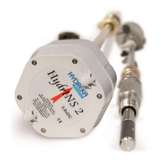
3 Description of the HydrINS2 / HydrINS 2 Mini product range 3.1 Mechanical description: Alignment stem Probe head with orientation arrow Communication port and pulse output Insertion marking Clamp ring Pressure output Sensor Figure 8: Mechanical description of the HydrINS 2 / HydrINS 2 Mini flow meter... -
Page 16: Figure 9: Drawing Of Hydrins 2 And Hydrins 2 Mini Probes
*A: dimension A is 689(27.12) for Cat. No.: SI_HYDA2P-30 / 869(34.2) for Cat. No. SI_HYDA2P-50 / 1109(43.66) for SI_HYDA2P-70 / 1409(55.47) for SI_HYDA2P-100 / 500(19.68) for Cat. No. SI_HYDE2-15 Dimensions in mm (inches) Figure 9: Drawing of HydrINS 2 and HydrINS 2 Mini probes... -
Page 17: Models In The Hydrins 2 / Hydrins 2 Mini Flow Meter Range
3.2 Models in the HydrINS 2 / HydrINS 2 Mini flow meter range The following table is a selection guide to identify the most appropriate HydrINS 2 model according to the pipe diameter and dimensions as shown in the diagram above: ... - Page 18 610 (24) Table 7: Clearance heights above the insertion point required for installation of a HydrINS 2 / HydrINS 2 Mini flow meter. Appendix 1 presents the HydrINS 2 / HydrINS 2 Mini flow meter models that can be used for several...
-
Page 19: Installation Location Of The Hydrins 2 / Hydrins 2 Mini Flow Meter
Page 19 / 79 Installation Manual 4 Installation location of the HydrINS 2 / HydrINS 2 Mini flow meter 4.1 Choice of installation location and installation and flow conditions For accurate measurement of the flow, the pipe must be continuously carrying a flow, and disturbance-free upstream and downstream distances ('straight lengths') must be observed. -
Page 20: Velocity Limits For Measurement
The creation of a velocity profile is used to refine the insertion factor and profile factor values (refer to the HydrINS 2 / HydrINS 2 Mini flow meter acquisition programming manual). The order of magnitude of the maximum velocities to be observed are indicated on the chart below. -
Page 21: Choice Of Position For The Electromagnetic Sensor
HydrINS 2 / HydrINS 2 Mini flow meter Page 21 / 79 Installation Manual Figure 12: Orders of magnitude of maximum velocities not to be exceeded to create a velocity profile 4.3 Choice of position for the electromagnetic sensor Two precise positions are chosen for the electrodes in order to take a flow measurement: ... -
Page 22: Typical Installation Of Hydrins 2 / Hydrins 2 Mini Flow Meters
Or 3/4" insertion – drill 19 mm (0.75 inches) minimum: does not need an adapter. The preparation of an insertion point compatible with HydrINS 2 or HydrINS 2 Mini is exactly the same as for the preparation of a classic insertion point for the installation of a connection. No additional accessories are required. -
Page 23: Inside Diameter Measurement Gauges
HydrINS 2 / HydrINS 2 Mini flow meter Page 23 / 79 Installation Manual 4.5 Inside diameter measurement gauges Before the probe is installed, measurements may be performed using an adaptable diameter gauge on a 1" insertion thread. Their use requires the appropriate clearance above the pipe. -
Page 24: Installation Of The Hydrins 2 / Hydrins 2 Mini Flow Meter
HydrINS 2 / HydrINS 2 Mini flow meter Page 24 / 79 Installation Manual 5 Installation of the HydrINS 2 / HydrINS 2 Mini flow meter 5.1 Method for installation at the centre: The method for installing the probe at the centre, described below, includes three stages: 1. -
Page 25: Step 1/3: Measuring The Inside Diameter Di Using The Gauge
HydrINS 2 / HydrINS 2 Mini flow meter Page 25 / 79 User Manual 5.1.1 Step 1/3: Measuring the inside diameter DI using the gauge Freely Immobilised rotating ring ring Ring A Ring B Tighten the diameter gauge, 1. Open the insert valve and lower 1. -
Page 26: Step 2/3: Measure Length Of Insertion At The Centre Li 1/2
HydrINS 2 / HydrINS 2 Mini flow meter Page 26 / 79 User Manual 5.1.2 Step 2/3: Measure length of insertion at the centre 1. From the last position, 1. Raise the gauge fully. 1. Tighten Ring B. place Ring A half-way along 2. -
Page 27: Step 3/3: Probe Insertion
HydrINS 2 / HydrINS 2 Mini flow meter Page 27 / 79 User Manual 5.1.3 Step 3/3: Probe insertion Installation at the centre 1. Close the insertion valve, tighten the probe, and lower the probe until it stops on the ball of the valve. -
Page 28: Method For Installation At 1/8
HydrINS 2 / HydrINS 2 Mini flow meter Page 28 / 79 User Manual 5.2 Method for installation at 1/8 For an installation at 1/8 diameter, the distance Z after probe insertion must be equal to: = L - E - 1/8 DI ... -
Page 29: Aligning The Guide Bar With The Direction Of Flow
The orientation of the HydrINS 2/ HydrINS 2 Mini flow meter must now be adjusted. The head of the HydrINS 2 / HydrINS 2 Mini flow meter has a red arrow to orient the flow meter in the main direction of flow. Flow in this direction will count as positive, whilst flow in the reverse direction will count as negative. -
Page 30: Installing The Pressure Channel On A Data Recorder
User Manual 6 Installing the pressure channel on a data recorder The HydrINS 2 / HydrINS 2 Mini insertion flow meter has a Quickfit connector to measure the pressure at the same point as the flow measurement. This channel can be connected to a recorder with an internal pressure channel (10 or 20 bars). This applies to Lolog, Vista +, Octopus LX and other recorders. -
Page 31: Viewing Measurements By Display Or Recording
20-28 volts) with two 4-20 mA outputs (on terminal block) and four pulse outputs (two on terminal block, two on output connector). The HydrINS 2/HydrINS 2 Mini flow meter operates in two separate modes: Mode 1 (without Display): The flow meter operates in standalone mode thanks to two batteries in the head of the flow meter. -
Page 32: Installation Of A Display
Figure 20: Installation configurations for HydrINS 2 / HydrINS 2 Mini It is essential to ensure that the HydrINS 2 / HydrINS 2 Mini flow meter is configured in the appropriate operating mode before placing it in operation; otherwise, the probe will suffer irreversible damage (see paragraph 8.2). -
Page 33: Mounting The Display Unit On A Wall
HydrINS 2 / HydrINS 2 Mini flow meter Page 33 / 79 User Manual Magnetic switch Figure 21: Application of the magnet to the magnetic switch to activate the Display 8.2 Mounting the display unit on a wall The Display can be mounted according to the following dimensions: The substrate must have a perfectly flat surface. -
Page 34: Mode Change Of The Hydrins 2 And Hydrins 2 Mini Probes
The change of the probe power supply mode must be performed with care. If not, there is a risk of causing severe electrical damage to the flow meter. 8.3.1 Equipment The following equipment is required to remove the HydrINS 2/HydrINS 2 Mini probe head: Flat head screwdriver ... -
Page 35: Figure 24: Overview Of The Inside Of The Hydrins 2 Flow Meter Head
(and mode) identification Light to switch between modes without the need to remove the yellow battery holder. Figure 24: Overview of the inside of the HydrINS 2 flow meter head Loosen the three flat-head screws securing the battery holder, and remove it. -
Page 36: Mode Change
HydrINS 2 / HydrINS 2 Mini flow meter Page 36 / 79 User Manual Figure 25: Removal of the cover from the head of the HydrINS 2 flow meter 8.3.3 Mode change According to the desired mode, set up the configuration described below:... -
Page 37: Figure 26: Mode 1/Mode 2 Change And Arrangement Of Batteries In The Hydrins 2 Flow Meter
Battery 1 kept connection Figure 26: Mode 1/Mode 2 change and arrangement of batteries in the HydrINS 2 flow meter Reinstall the cover using the alignment guides: Figure 27: Locating guides for the head of the HydrINS 2 flow meter Also be sure to reposition the foam, the new silicagel bag, and battery wire protectors (transparent plastic). - Page 38 HydrINS 2 / HydrINS 2 Mini flow meter Page 38 / 79 User Manual 8.4 Closing the display lids Follow the instructions below to close the lids of display units (A,C,E and G) 1. Put the first lid in place by pushing "A" point then "B" point", hold in place then screw points 1 and 2 at 0.85 Nm.
-
Page 39: Electrical Power Supply Of Display A
HydrINS 2 / HydrINS 2 Mini flow meter Page 39 / 79 User Manual 8.5 Electrical power supply of Display A Risk of electrocution. Always disconnect the power supply before making any electrical connections. Potential damage to the device. The internal electronic components of the device can be damaged by static electricity, which might affect its performance characteristics and operation. -
Page 40: Figure 28: Positions Of Connector J15 And Switch Sw2 Inside Display A
HydrINS 2 / HydrINS 2 Mini flow meter Page 40 / 79 User Manual Connector J15 Connector SW2 Figure 28: Positions of Connector J15 and Switch SW2 inside Display A In a case other than lithium battery power supply, an electronic board, Cat. No. 400511, is connected... -
Page 41: Internal Power Supply Using 3.6 Vdc Lithium Batteries
HydrINS 2 / HydrINS 2 Mini flow meter Page 41 / 79 User Manual 8.5.1 Internal power supply using 3.6 VDC lithium batteries 1 – Create the following configuration: Switch SW2: Internal Connector J15: Connect 1-2 and 15-16 2 –... -
Page 42: Internal Power Supply Using Alkaline Batteries
HydrINS 2 / HydrINS 2 Mini flow meter Page 42 / 79 User Manual 8.5.3 Internal power supply using alkaline batteries 1 – Remove all connections from Connector J15, and then connect the additional board, Cat. No., 4005511 to the same connector. In this case, the position of Switch SW2 used earlier is no longer relevant. -
Page 43: External Power Supply By Military Connector
HydrINS 2 / HydrINS 2 Mini flow meter Page 43 / 79 User Manual 8.5.5 External power supply by military connector For connection to the military connector, use a CNT104/CNT105 cable, and then connect the banana plugs to an external power supply. -
Page 44: Electrical Power Supply Of Display And Recording Unit
HydrINS 2 / HydrINS 2 Mini flow meter Page 44 / 79 User Manual Figure 32: Selection of the type of power supply for Display C 8.7 Electrical power supply of Display and Recording Unit Risk of electrocution. Always disconnect the power supply before making any electrical connections. -
Page 45: Wiring Of The Entities Of The Measurement Chain
Vista + (local recorder) Octopus LX Remote (SMS/GPRS) manageme Figure 33: Wiring possibilities from a HydrINS 2 / HydrINS 2 Mini flow meter without Display (Mode 1) Receiver Cat. No. of cable used CNT 90S Standalone recorder: Lolog, Vista +, etc. -
Page 46: Figure 34: Wiring Possibilities From A Hydrins 2 / Hydrins 2 Mini Flow Meter With Display (Mode 2)
(standalone recorder, SCADA or remote management) by connecting the Display and the acquisition system. To do this, use the same cables that were used to connect the HydrINS 2 / HydrINS 2 Mini flow meter and acquisition system, to connect the acquisition system to the Display communication military connector. -
Page 47: Figure 35: 4-20 Ma Outputs On Display C
HydrINS 2 / HydrINS 2 Mini flow meter Page 47 / 79 User Manual CNT 120S Computer, Tablet CC_HYDUSBS-3 (200 metres max) Display C 4-20 mA and/or pulses (Bare wires) Remote manageme Figure 35: 4-20 mA outputs on Display C Receiver Cat. -
Page 48: Internal Wiring
8.9.1 Connections of the HydrINS probe to the Display terminal block Each pin number on the military connector corresponds to a coloured wire at the other end of the cable connecting the HydrINS 2/HydrINS 2 Mini to the display. Figure 36: Diagram: connecting the HydrINS probe to the display... -
Page 49: Pulse Output Connections To The Display Terminal Block
HydrINS 2 / HydrINS 2 Mini flow meter Page 49 / 79 User Manual Pin Number on Probe Colour Display terminal block Connector designation BLACK - V IN (0V) + V IN PURPLE COM FRQ WHITE/YELLOW FRQ OUT 2 WHITE/BLUE... -
Page 50: Wiring The 4-20 Ma Outputs To The Terminal Block Of Display C
HydrINS 2 / HydrINS 2 Mini flow meter Page 50 / 79 User Manual Route the cable using the cable gland, and then fasten the various wires to the pulse connector according to the correspondence table below: Terminal block designation (output) -
Page 51: Table 6: Connections For The Active 4 - 20 Ma Outputs (Power Supplied By The Display Unit)
HydrINS 2 / HydrINS 2 Mini flow meter Page 51 / 79 User Manual Route the cable using the cable gland, and then fasten the various wires to the 4-20 mA connector according to the correspondence table below: Function Terminal block (4-20 mA outputs) SDU only... - Page 52 HydrINS 2 / HydrINS 2 Mini flow meter Page 52 / 79 User Manual 8.9.5 SIM insertion with AFFHYDG Insert the SIM card to the associated location, push the SIM card until it clicks (you should hear a "CLICK") in the guide.
-
Page 53: Technical Characteristics
HydrINS 2 / HydrINS 2 Mini flow meter Page 53 / 79 User Manual 9 Technical Characteristics: 9.1 Hydrins II Probe Two-way, from 0.02 m/s to 5 m/s, limited only by the stability and stiffness of the probe. Measurement range Fluid with conductivity of at least 20 µS/cm. -
Page 54: Display Units
HydrINS 2 / HydrINS 2 Mini flow meter Page 54 / 79 User Manual 9.2 Display units Two pulse outputs, opto-isolated open collectors. LCD screen: Timed or continuous backlit, two lines of Display A Maximum frequency: 50 Hz Pulse width: 10ms - 28V 16 characters 50 mA maximum - Max. -
Page 55: Maintenance
User Manual 10 Maintenance Maintenance of the HydrINS2 / HydrINS 2 Mini product is very easy: Simply remove the probe from the insert (ensure that the chain is taut when removing). This maintenance procedure is very economical and practical compared to the maintenance of an electromagnetic sleeve, for example. -
Page 56: Calibration
HYDREKA, which has a COFRAC-connected hydraulic bench for flow meter calibration. Figure 40: Hydraulic bench for the calibration of HydrINS 2 / HydrINS 2 Mini flow meters and HYDREKA calibration certificate A calibration certificate is issued at the end of the calibration phase (see Appendix 4). -
Page 57: Replacing The Batteries Of The Hydrins 2 / Hydrins 2 Mini Flow Meter
User Manual 11.2 Replacing the batteries of the HydrINS 2 / HydrINS 2 Mini flow meter Apply the following procedure to replace the batteries in the head of the HydrINS 2 / HydrINS 2 Mini flow meter: 1 – Open the head of the flow meter (see Para. 8.3). -
Page 58: Product Disposal
Page 58 / 79 User Manual Figure 42: Reinitialisation of battery levels in HydrINS 2 / HydrINS 2 Mini in Mode 2 with a Display A in Winfluid 12 Product disposal The product must be disposed of in accordance with local regulations concerning the... -
Page 59: Appendix 1: Selection Guide: The Right Hydrins 2 Model For Your Measurement Site According To Your Pipe
Manual Appendix 1: Selection Guide: The right HydrINS 2 model for your measurement site according to your pipe The following table shows the compatibility of standardised diameters with the available HydrINS 2 / HydrINS 2 Mini models Steel HydrINS 2... - Page 60 HydrINS 2 / HydrINS 2 Mini Flow Meter User Page 60 / 79 Manual Asbestos - Cement HydrINS 2 HydrINS 2 HydrINS 2 HydrINS 2 HydrINS 2 Mini "300" "500" "700" "1000" Inside Inside Type of Speed Speed Speed Speed...
- Page 61 HydrINS 2 / HydrINS 2 Mini Flow Meter User Page 61 / 79 Manual HDPE HydrINS 2 HydrINS 2 HydrINS 2 HydrINS 2 HydrINS 2 Mini "300" "500" "700" "1000" Inside Inside Type of Speed Speed Speed Speed Speed Material...
- Page 62 HydrINS 2 / HydrINS 2 Mini Flow Meter User Page 62 / 79 Manual PVC PN 10 HydrINS 2 HydrINS 2 HydrINS 2 HydrINS 2 HydrINS 2 Mini "300" "500" "700" "1000" Inside Inside Type of Speed Speed Speed Speed...
- Page 63 HydrINS 2 / HydrINS 2 Mini Flow Meter User Page 63 / 79 Manual PVC PN 16 HydrINS 2 HydrINS 2 "300" HydrINS 2 "500" HydrINS 2 "700" HydrINS 2 Mini "1000" Inside Inside Speed Speed Speed Speed Speed Centre...
- Page 64 HydrINS 2 / HydrINS 2 Mini Flow Meter User Page 64 / 79 Manual K9 Ductile Cast Iron HydrINS 2 HydrINS 2 HydrINS 2 HydrINS 2 HydrINS 2 Mini "300" "500" "700" "1000" Inside Inside Type of Speed Speed Speed...
- Page 65 HydrINS 2 / HydrINS 2 Mini Flow Meter User Page 65 / 79 Manual C40 Ductile Cast Iron HydrINS 2 HydrINS 2 HydrINS 2 HydrINS 2 HydrINS 2 Mini "300" "500" "700" "1000" Inside Inside Type of Speed Speed Speed...
- Page 66 HydrINS 2 / HydrINS 2 Mini Flow Meter User Page 66 / 79 Manual Grey cast iron HydrINS 2 HydrINS 2 HydrINS 2 HydrINS 2 HydrINS 2 Mini "300" "500" "700" "1000" Inside Inside Type of Speed Speed Speed Speed...
- Page 67 HydrINS 2 / HydrINS 2 Mini Flow Meter User Page 67 / 79 Manual Bonna Sabla HydrINS 2 HydrINS 2 HydrINS 2 HydrINS 2 HydrINS 2 Mini "300" "500" "700" "1000" Inside Inside Type of Speed Speed Speed Speed Speed...
-
Page 68: Appendix 2: Inside Diameter Gauges
1000 (3.28) 1200 (3.94) JD_HYD10A-125 900 (2.95) 1" NPT 1250 (4.1) 1450 (4.76) JD_HYD20A-100 700 (2.3) 2" NPT 1000 (3.28) 1200 (3.94) JD_HYD20A-125 900 (2.95) 2" NPT 1250 (4.1) 1450 (4.76) Table 7: Descriptive characteristics of diameter gauges marketed by HYDREKA... -
Page 69: Hydrins 2 Products
Catalogue Numbers associated with the range of HydrINS 2 / HydrINS 2 products HydrINS 2 flow meters HydrINS 2 insertion flow meter - Model 300 - BSP SI_HYDA2P-30 thread HydrINS 2 insertion flow meter - Model 500 - BSP SI_HYDA2P-50... - Page 70 Communication leads HydrINS probe digital output cable - RADCOM CNT102S recorders HydrINS 2 - Display signal output cable, 5 m CNT120S -5 HydrINS 2 - Display signal output cable, 10 m CNT120S- 10 HydrINS 2 digital output cable, two bare wires,...
- Page 71 HydrINS 2 / HydrINS 2 Mini Flow Meter Page 71 / 79 User Manual Gauges BSP thread 1" BSP gauge - dia. 500 mm max. JD_HYD_10-088 1" BSP gauge - dia. 700 mm max. JD_HYD_10-1000 1" BSP gauge - dia. 900 mm max.
- Page 72 HydrINS 2 / HydrINS 2 Mini Flow Meter Page 72 / 79 User Manual PELICASE cases Waterproof case (908 x 351 x 133 mm inside) for VALPEL1700 HydrINS 300 Waterproof case (1060 x 343 x 133 mm inside) for VALPEL1720...
-
Page 73: Appendix 4: Template For Hydreka Calibration Certificate For The Hydrins
HydrINS 2 / HydrINS 2 Mini Flow Meter Page 73 / 79 User Manual Appendix 4: Template for HYDREKA calibration certificate for the HydrINS 2 / HydrINS 2 Mini flow meter... -
Page 74: Table Of Illustrations
Figure 4: Typical packaging of the HydrINS2/HydrINS 2 Mini ............... 12 Figure 5: Pelicase transport case ......................13 Figure 6: HydrINS 2 / HydrINS 2 Mini guide bar connected to the flow meter in the packaging ..14 Figure 7: Flow meter protection plug ....................14 Figure 8: Mechanical description of the HydrINS 2 / HydrINS 2 Mini flow meter ........ - Page 75 Figure 41: Reinitialisation of the battery levels in HydrINS 2 in Mode 1 in Winfluid ......57 Figure 42: Reinitialisation of battery levels in HydrINS 2 / HydrINS 2 Mini in Mode 2 with a Display A in Winfluid ............................. 58...
-
Page 76: List Of Tables
Table 2: Correspondence of lengths L with the HydrINS probe model for an installation at 1/8th diameter ..............................28 Table 3: Wiring of HydrINS 2 / HydrINS 2 outputs in Mode 1 ............... 45 Table 4: Cable connections according to colour and terminal block designation ........ 49 Table 5: Connection of pulse outputs –... - Page 77 HydrINS 2 / HydrINS 2 Mini Flow Meter Page 77 / 79 User Manual NOTES...
- Page 78 HydrINS 2 / HydrINS 2 Mini Flow Meter Page 78 / 79 User Manual NOTES...
- Page 79 HydrINS 2 / HydrINS 2 Mini Flow Meter Page 79 / 79 User Manual NOTES HYDREKA 34, route de Saint Romain – 69450 ST CYR AU MONT D’OR – France Tel: +33 (0)4 72 53 11 53 – Fax: +33 (0)4 78 83 44 37 Email: hydreka@hydreka.fr...
Need help?
Do you have a question about the HydrINS 2 and is the answer not in the manual?
Questions and answers