Sign In
Upload
Manuals
Brands
Hydreka Manuals
Measuring Instruments
HydrINS 2 Mini
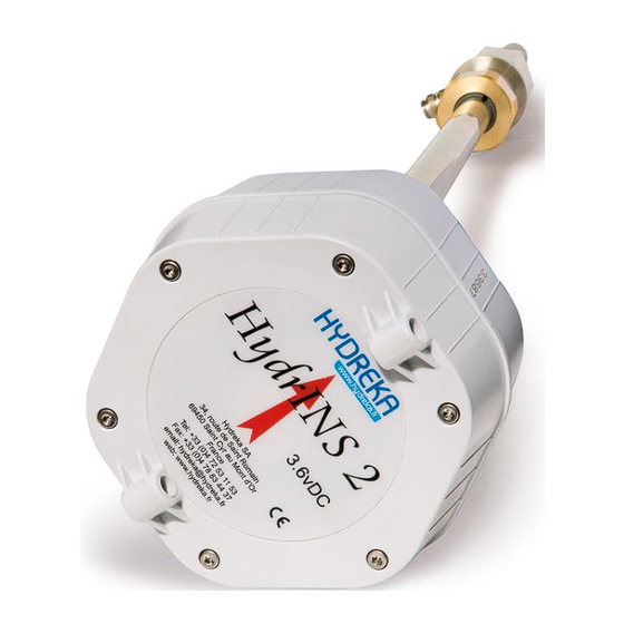
Hydreka HydrINS 2 Mini Manuals
Manuals and User Guides for Hydreka HydrINS 2 Mini. We have
3
Hydreka HydrINS 2 Mini manuals available for free PDF download: Installation Manual, Programming Manual
Hydreka HydrINS 2 Mini Programming Manual (77 pages)
electromagnetic insertion flow meters
Brand:
Hydreka
| Category:
Measuring Instruments
| Size: 3 MB
Table of Contents
Hydrins 2 and Hydrins 2 Mini Electromagnetic Insertion Flow Meters Programming of Data Logging
2
Table of Contents
2
1 Introduction
6
2 Basic Programming of Hydrins 2 / Hydrins 2 Mini Flow Meters
6
Figure 1: General Configuration of Winfluid - Situation of the Parameters Menu on the Home Screen
6
Configuration of the Digital Channel of the Hydrins 2 Probe
7
Figure 2: View of the Winfluid Home Screen
7
General Tab
7
Figure 3: Overview of the Sensor Tab
8
Sensor Tab
8
Figure 4: Programming Window for the Hydrins 2 Probe
9
Figure 5: Overview of the Hydrins 2 Probe Programming Window - General Tab
9
General Tab
9
Figure 6: Overview of the Hydrins 2 Probe Programming Window - General Tab - Maximum Allowable Flow Rate to be Observed
10
Display Tab
11
Strategy and Other Tabs
11
Transmission of the Programming
11
Direct Transmission of the Programming to the Hydrins 2 / Hydrins 2 Mini Flow Meter
11
Figure 7: Overview of the Hydrins 2 Probe Programming Window
11
Figure 8: Connection of the CC_HYDA3 or CC_HYDA3S Cable to the Flow Meter
12
Figure 9: Connection Dialogues for Programming
12
Figure 10: Correct Programming Confirmation Dialogues
13
Transmission of the Programming to the Flow Meter During Programming of the Associated Standalone Data Logger
13
Figure 11: Programming Dialogue
14
Figure 12: Connection Dialogues for Flow Meter Programming
14
Figure 13: Correct Programming Confirmation Dialogues
14
Figure 14: Connection Dialogue for Programming
15
Figure 15: Preview Window before Launching Acquisition by the Data Logger
15
Real-Time Reading
16
Taking a Reading of Recorded Data
16
Figure 16: Status Acquisition Window
16
3 Retrieval / Programming of the Flow Meter
17
Retrieval of the Programming to the Hydrins 2 / Hydrins 2 Mini Flow Meter
17
Figure 17: Retrieval of the Flow Meter Programming from the Main Winfluid Screen
17
Programming of a Hydrins 2 / Hydrins 2 Mini Flow Meter
18
Figure 18: Retrieval of the Flow Meter Programming from the Main Winfluid Screen
18
Figure 19: Programming the Flow Meter from the Main Winfluid Screen
18
4 Advanced Programming of the Hydrins2 Probe
19
Programming of Hydrins 2 and Hydrins 2 Mini Flow Meters in Advanced Mode
19
Figure 20: Programming the Flow Meter from the Main Winfluid Screen
19
Conversion Tab
20
Figure 21: Position of the Advanced Button in the Flow Meter Programming Window
20
Figure 22: Password Input Window
20
Figure 23: Advanced Mode - Conversion Tab
20
Figure 24: Flow Signal Saturation Warning Window
21
Calculation Tab
22
Figure 25: Advanced Mode - Sampling Tab
22
Figure 26: Advanced Mode - Calculation Tab
22
Sampling Tab
22
Figure 27: Advanced Mode - 4-20 Ma Tab
23
Ma Tab
23
Figure 28: Advanced Mode - Maintenance Tab
24
Maintenance Tab
24
Instrument Tab
25
Real-Time Monitoring of Recording (to Pre-Locate Leaks by Operating the Step-Test Valves, for Example)
25
Figure 29: Advanced Mode - Instrument Tab
25
Figure 30: Selecting the Computer as Data Logger
26
Configuration
27
Figure 31: Winfluid Home Screen with the Computer as Data Logger
27
Figure 32: Real-Time Display in Computer Mode
28
Use of the Enabled 4-20 Ma Outputs (Display C)
29
Figure 33: Flow Curve
29
Figure 34: Enabling the 4-20 Ma Output of the Display During Programming
30
Figure 35: Display C 4-20 Ma Output Calibration Icon
30
Figure 36: Display C 4-20 Ma Output Calibration Icon
31
Figure 37: Checking the 4-20 Ma Output Using an Ammeter
31
Calculating a Velocity Profile Using the Hydrins 2 / Hydrins 2 Mini Probe
32
Figure 38: Velocity Profile - Maximum Velocities for the Creation of a Velocity Profile
32
Introduction
32
Configuration
33
Figure 39: Launching the Velocity Profile Program from Advanced Mode
33
Figure 40: Launching the Velocity Profile Program from the Winfluid Home Screen
33
Launching the Velocity Profile Program
33
Figure 41: Velocity Profile Editing Window
34
Figure 42: Velocity Profile Editing Window
34
Figure 43: Velocity Profile Measurement Window
35
Measurement
35
Figure 44: Connection of the CC_HYDA3 or CC_HYDA3S Cable to the Flow Meter
36
Figure 45: Probe Routing for the Velocity Profile Measurement
36
Figure 46: Velocity Profile Measurement Window
37
Measurement Procedure
39
Figure 47: Measuring of Probe Raising for the Creation of a Velocity Profile
40
Figure 48: Measurement Point Confirmation Window
41
Processing a Profile
43
Figure 49: Velocity Profile Preview Screen
43
Opening a Velocity Profile
43
Copying a Profile File
44
Deleting a Profile File
44
Figure 50: Measurement Opening Window
44
Figure 51: Selection Window for Measurements to be Copied
44
Figure 52: Copy Destination Directory Selection Window
45
Modifying a Velocity Profile File
45
Printing and Exporting Data from a Velocity Profile
45
Figure 53: Velocity Profile Measurement Export Window
46
Programming a Profile Previously Saved
46
Figure 54: Flow Meter Programming Window with Velocity Profile
47
Figure 55: Programming the Velocity Profile
47
Transferring a Velocity Profile to Winfluid
47
Figure 56: Sending the Velocity Profile Programming to Winfluid
48
Figure 57: Window to Send Coefficients to Winfluid
48
Synchronisation of Pc/Pocket PC Profile Files
49
5 Hydrins Display Software
49
Figure 58: Pocket PC to PC Synchronisation Window
49
Figure 59: Access to the Hydrins Display Management Window
50
Figure 60: Hydrins Display Tool - Access to Configuration
50
Figure 61: Hydrins Display Tool - Configuration
51
Figure 62: Hydrins Display Tool - Display Configuration
51
Figure 63: Hydrins Display Tool - Connection
52
Figure 64: Hydrins Display Tool - Real-Time Display
52
6 Remote Assistance
53
Figure 65: Hydrins Display Tool - Reset Totalisers
53
Figure 66: Hydrins Display Tool - Reset Totalisers - Confirmation
53
Figure 67: Launching Remote Assistance
54
Figure 68: Connection Information for Remote Assistance
54
7 Maintenance
55
Figure 69: Checking the Current Version of Winfluid on the Home Screen
55
Figure 70: Displaying the about Winfluid Section
56
Figure 71: Updating Winfluid from the Main Screen
56
8 Hydrins Software
57
Figure 72: Winfluid Update - Selecting the Update Frequency
57
Figure 73: Winfluid Update - Displaying the Update Information
57
Configuration
58
Figure 74: Hydrins Software - Hydrins Software Home Screen
58
Content of Menus
59
Figure 75: Hydrins Software - Configuration of the Workspace
59
Figure 76: Hydrins Software - List of Tasks Available in the 'Sensor' Menu
59
Sensor Menu
59
Figure 77: Hydrins Software - List of Tasks Available in the 'File' Menu
60
Figure 78: Hydrins Software - File Opening Window
60
Figure 79: Hydrins Software - File Saving Window
60
File Menu
60
Figure 80: Hydrins - Software List of Tasks Available in the 'Maintenance' Menu
61
Figure 81: Serial Output Test Window
61
Maintenance Menu
61
Figure 82: Hydrins Software - Battery Level Display Window
62
Figure 83: Hydrins Software - 4-20 Ma Output Calibration Window
62
Information Displayed
63
Figure 84: Hydrins Software - Output Value Simulation Window
63
Figure 85: Hydrins Software - Hydrins Software Home Window
63
Identification Box
63
Installation Box
64
Sampling Box
64
Units Box
64
Calculation Box
65
Calibration Box
65
Serial Output Tab
65
Figure 86: Hydrins Software - Serial Output Tab Window
66
Display Tab
67
Figure 87: Hydrins Software - 4-20 Ma Programming Window
67
Ma Output Tab
67
Figure 88: Hydrins Software - Display Configuration Window
68
Appendix 1: Velocity Profile Printing Template
69
Appendix 1: Associated Hydreka Catalogue Numbers
70
Table of Illustrations
71
Advertisement
Hydreka HydrINS 2 Mini Installation Manual (73 pages)
Electromagnetic Insertion Flow Meters
Brand:
Hydreka
| Category:
Measuring Instruments
| Size: 2 MB
Table of Contents
Table of Contents
2
Introduction
6
Measurement Principle
7
Figure 1: Location of Sensor on the Hydrins2/Hydrins 2 Mini Flow Meter
7
Environmental and Safety Conditions
8
Conditions in the Measurement Environment
8
Figure 2: Hydrins 2/Hydrins 2 Mini Data Processing System
8
Software Environment
9
Safety
9
Product Transport
10
Figure 3: Safety Chain
10
Figure 4: Typical Packaging of the Hydrins2/Hydrins 2 Mini
10
Figure 5: Pelicase Transport Case
11
Figure 7: Flow Meter Protection Plug
12
Conditioning the Product before Use
12
Figure 6: Hydrins 2 / Hydrins 2 Mini Guide Bar Connected to the Flow Meter in the Packaging
12
Product Guarantee
12
Description of the Hydrins2/Hydrins 2 Mini Product Range
13
Mechanical Description
13
Figure 8: Mechanical Description of the Hydrins 2 / Hydrins 2 Mini Flow Meter
13
Figure 9: Drawing of the Hydrins 2 and Hydrins 2 Mini Probes
14
Models in the Hydrins 2 / Hydrins 2 Mini Flow Meter Range
15
Installation Location of the Hydrins 2 / Hydrins 2 Mini Flow Meter
17
Choice of Installation Location and Installation and Flow Conditions
17
Figure 10: Flow Conditions to be Observed
17
Velocity Limits for Measurement
18
Figure 11: Maximum Velocity for Different Pipe Internal Diameters
18
Table 1: Upstream Disturbance-Free Straight Lengths to be Observed
18
Figure 13: Valid Positions of the Hydrins2/Hydrins 2 Mini Flow Meter Sensor for Flow Measurement
19
Figure 12: Orders of Magnitude of Maximum Velocities Not to be Exceeded to Create a Velocity Profile
19
Choice of Position for the Electromagnetic Sensor
19
Figure 14: Diagram for the Adaptation of Different Threads for the Installation of the Hydrins 2/Hydrins 2 Mini Flow Meter
20
Valve Diagram for the Installation of Hydrins 2 / Hydrins 2 Mini Flow Meters
20
Inside Diameter Measurement Gauges
21
Figure 15: View of the Different Components of the Diameter Gauge
21
Figure 16: Gauge Pressure Evacuator
22
Installation of the Hydrins 2 / Hydrins 2 Mini Flow Meter
23
Method for Installation at the Centre
23
Step 1/3: Measuring the Inside Diameter ID Using the Gauge
24
Step 2/3: Measurement of Insertion Length at the Centre LI 1/2
25
Step 3/3: Insertion of the Probe
26
Method for Installation at 1/8
27
Figure 17: Diagram of Installation at 1/8 Diameter
27
Table 2: Correspondence of Lengths L with the Hydrins Probe Model for an Installation at
27
Figure 19: Aligning the Flow Meter in the Direction of Flow
28
Aligning the Guide Bar with the Direction of Flow
28
Figure 18: Position of the Positive Direction Arrow on the Probe Head
28
Installing the Pressure Channel on a Data Logger
29
Processing of Data Measured by Display or Recording
29
Figure 20: Quickfit Connector for the Pressure Channel between Data Logger and Probe
29
Installation of a Display a or a Display C
31
Overview of Displays a and C
31
Figure 21: Installation Configurations for Hydrins 2/Hydrins 2 Mini
31
Figure 22: Inputs and Outputs of Displays a and C
32
Table 3: Outputs of Displays a and C
32
Wall Mounting of Display a or Display C
33
Figure 23: Application of the Magnet to the Magnetic Switch to Activate the Display
33
Figure 24: Layout Diagram for the Wall Mounting of a Display a or C
33
Figure 25: Remove the Screws from the Head of the Hydrins 2 Flow Meter
34
Equipment
34
Removal
34
Mode Change of the Hydrins 2 and Hydrins 2 Mini Probes
34
Figure 26: Overview of the Inside of the Hydrins 2 Flow Meter Head
35
Figure 27: Removal of the Head of the Hydrins 2 Flow Meter from the Compartment
35
Mode Change
36
Electrical Power Supply of Display a
36
Figure 28: Mode 1/Mode 2 Change and Arrangement of Batteries in the Hydrins 2 Flow Meter
36
Figure 29: Locating Guides for the Head of the Hydrins 2 Flow Meter
36
Internal Power Supply Using 3.6 VDC Lithium Batteries
37
Figure 30: Positions of Connector J15 and Switch SW2 Inside Display a
37
External Power Supply Using 3.6 VDC Lithium Batteries
38
Figure 31: Connection of the Lithium Battery
38
Figure 32: Position to Use for an External 3.6 V Power Supply
38
Figure 33: Position to Use for an External 9-28 V Power Supply
39
External 9 to 28 VDC Power Supply Connected to the Internal Terminals
39
Internal Power Supply Using Alkaline Batteries
39
Electrical Power Supply of Display C
40
Figure 34: Power Supply of a Display a with CNT 104 or CNT 105
40
External Power Supply by Military Connector
40
Figure 35: Selection of the Type of Power Supply for Display C
41
Figure 36: Power Supply of a Display C with CNT 104 or CNT 105
41
Wiring of the Entities of the Measurement Chain
42
Figure 37: Wiring Possibilities from a Hydrins 2 / Hydrins 2 Mini Flow Meter Without Display
42
Figure 38: Wiring Possibilities from a Hydrins 2 / Hydrins 2 Mini Flow Meter with Display (Mode 2)
43
Figure 39: 4-20 Ma Outputs on Display C
44
Internal Wiring
45
Connections of the Flow Meter Pulse Output to the Display Terminal Block
45
Figure 40: Output Connector Pin Correspondence Diagram
45
Figure 41: Output Connector Pin Correspondence Diagram
45
Table 6: Pulse Output Connections - Terminal Block Designation - Output
46
Pulse Output Connections to the Display Terminal Block
46
Figure 42: Location of Pulse Outputs
46
Table 5: Cable Connections According to Their Colour and Terminal Designation
46
Wiring the 4-20 Ma Outputs to the Terminal Block of Display C
47
Figure 43: Connection of Pulse Outputs to Terminal Block
47
Figure 44: Location of the 4-20 Ma Outputs (Display C)
47
Table 7: Connections for the Active 4 - 20 Ma Outputs (Power Supplied by the Display Unit)
47
Protecting the Displays from Lightning and Surges
48
Figure 45: Connection of the Pulse Outputs to the Terminal Block of Display C
48
Maintenance
49
Figure 46: Lightning Protection of Display C
49
Figure 47: Maintenance of a Flow Meter Measuring Water Loaded with Metal Particles
50
Figure 48: Hydraulic Bench for the Calibration of Hydrins 2/ Hydrins 2 Mini Flow Meters and HYDREKA Calibration Certificate
50
Calibration
50
Maintenance
50
Replacing the Batteries of the Hydrins 2 / Hydrins 2 Mini Flow Meter
51
Replacing the Batteries in Display a
51
Figure 49: Reinitialisation of the Battery Levels in Hydrins 2 in Mode 1 in Winfluid
51
In Winfluid
51
Product Disposal
52
Figure 50: Reinitialisation of Battery Levels in Hydrins 2 / Hydrins 2 Mini in Mode 2 with a Display a
52
Appendix 1: Selection Guide - the Right Hydrins 2 Model for Your Measurement Site According to Your Pipe
53
Appendix 2: Inside Diameter Gauges
62
Hydrins 2 Mini Products
63
Appendix 4: Template for Hydreka Calibration Certificate for the Hydrins
67
Hydrins 2 Mini Flow Meter
67
Table of Illustrations
68
List of Tables
70
Hydreka HydrINS 2 Mini Installation Manual (79 pages)
Electromagnetic Insertion Flow Meters
Brand:
Hydreka
| Category:
Measuring Instruments
| Size: 2 MB
Table of Contents
Table of Contents
2
1 Safety Instructions
6
2 Introduction
8
Measurement Principle
9
Figure 1: Location of the Sensor on the Hydrins2/Hydrins 2 Mini Flow Meter
9
Environmental and Safety Conditions
10
Conditions in the Measurement Environment
10
Figure 2: Hydrins 2/Hydrins 2 Mini Data Processing System
10
Safety
11
Product Transport
12
Figure 3: Safety Chain
12
Figure 4: Typical Packaging of the Hydrins2/Hydrins 2 Mini
12
Figure 5: Pelicase Transport Case
13
Product Guarantee
14
Conditioning the Product before Use
14
Figure 6: Hydrins 2 / Hydrins 2 Mini Guide Bar Connected to the Flow Meter in the Packaging
14
Figure 7: Flow Meter Protection Plug
14
3 Description of the Hydrins2/Hydrins 2 Mini Product Range
15
Mechanical Description
15
Figure 8: Mechanical Description of the Hydrins 2 / Hydrins 2 Mini Flow Meter
15
Figure 9: Drawing of Hydrins 2 and Hydrins 2 Mini Probes
16
Models in the Hydrins 2 / Hydrins 2 Mini Flow Meter Range
17
4 Installation Location of the Hydrins 2 / Hydrins 2 Mini Flow Meter
19
Choice of Installation Location and Installation and Flow Conditions
19
Figure 10: Flow Conditions to be Observed
19
Velocity Limits for Measurement
20
Figure 11: Maximum Velocity for Different Pipe Internal Diameters
20
Table 1: Upstream Disturbance-Free Straight Lengths to be Observed
20
Choice of Position for the Electromagnetic Sensor
21
Figure 12: Orders of Magnitude of Maximum Velocities Not to be Exceeded to Create a Velocity Profile
21
Typical Installation of Hydrins 2 / Hydrins 2 Mini Flow Meters
22
Figure 13: Valid Positions of the Hydrins 2/Hydrins 2 Mini Flow Meter Sensor for Flow Measurement
22
Inside Diameter Measurement Gauges
23
Figure 14: View of the Different Components of the Diameter Gauge
23
Figure 15: Gauge Pressure Evacuator
23
5 Installation of the Hydrins 2 / Hydrins 2 Mini Flow Meter
24
Method for Installation at the Centre
24
Step 1/3: Measuring the Inside Diameter DI Using the Gauge
25
Step 2/3: Measure Length of Insertion at the Centre LI 1/2
26
Step 3/3: Probe Insertion
27
Method for Installation at 1/8
28
Figure 16: Diagram of Installation at 1/8 Diameter
28
Table 2: Correspondence of Lengths L with the Hydrins Probe Model for an Installation at 1/8Th Diameter
28
Aligning the Guide Bar with the Direction of Flow
29
Figure 17: Position of the Positive Direction Arrow on the Probe Head
29
Figure 18: Aligning the Flow Meter in the Direction of Flow
29
6 Installing the Pressure Channel on a Data Recorder
30
Figure 19: Quickfit Connector for the Pressure Channel between Recorder and Probe
30
7 Viewing Measurements by Display or Recording
31
8 Installation of a Display
32
Preview of Displays
32
Figure 20: Installation Configurations for Hydrins 2 / Hydrins 2 Mini
32
Mounting the Display Unit on a Wall
33
Figure 21: Application of the Magnet to the Magnetic Switch to Activate the Display
33
Figure 22: Dimensions for Wall-Mounting a Display
33
Mode Change of the Hydrins 2 and Hydrins 2 Mini Probes
34
Equipment
34
Removal
34
Figure 23: Remove the Screws from the Head of the Hydrins 2 Flow Meter
34
Figure 24: Overview of the Inside of the Hydrins 2 Flow Meter Head
35
Mode Change
36
Figure 25: Removal of the Cover from the Head of the Hydrins 2 Flow Meter
36
Figure 26: Mode 1/Mode 2 Change and Arrangement of Batteries in the Hydrins 2 Flow Meter
37
Figure 27: Locating Guides for the Head of the Hydrins 2 Flow Meter
37
Electrical Power Supply of Display a
39
Figure 28: Positions of Connector J15 and Switch SW2 Inside Display a
40
Internal Power Supply Using 3.6 VDC Lithium Batteries
41
External Power Supply Using 3.6 VDC Lithium Batteries
41
Figure 29: Connection of the Lithium Battery
41
Figure 30: Position to Use for an External 3.6 V Power Supply
41
Internal Power Supply Using Alkaline Batteries
42
External 9 to 28 VDC Power Supply Connected to the Internal Terminals
42
Figure 31: Position to Use for an External 9-28 V Power Supply
42
External Power Supply by Military Connector
43
Electrical Power Supply of Display C
43
Electrical Power Supply of Display and Recording Unit
44
Figure 32: Selection of the Type of Power Supply for Display C
44
Wiring of the Entities of the Measurement Chain
45
Figure 33: Wiring Possibilities from a Hydrins 2/Hydrins 2 Mini Flow Meter Without Display (Mode 1)
45
Table 3: Wiring of Hydrins 2 / Hydrins 2 Outputs in Mode 1
45
Figure 34: Wiring Possibilities from a Hydrins 2 / Hydrins 2 Mini Flow Meter with Display (Mode 2)
46
Figure 35: 4-20 Ma Outputs on Display C
47
Internal Wiring
48
Connections of the Hydrins Probe to the Display Terminal Block
48
Figure 36: Diagram: Connecting the Hydrins Probe to the Display
48
Pulse Output Connections to the Display Terminal Block
49
Figure 37: Location of Pulse Outputs
49
Table 4: Cable Connections According to Colour and Terminal Block Designation
49
Wiring the 4-20 Ma Outputs to the Terminal Block of Display C
50
Figure 38: Location of the 4-20 Ma Outputs (Display C)
50
Table 5: Connection of Pulse Outputs - Terminal Block Designation - Output
50
Table 6: Connections for the Active 4 - 20 Ma Outputs (Power Supplied by the Display Unit)
51
9 Technical Characteristics
53
Hydrins II Probe
53
Display Units
54
10 Maintenance
55
Figure 39: Maintenance of a Flow Meter Measuring Water Loaded with Metal Particles
55
Calibration
56
Figure 40: Hydraulic Bench for the Calibration of Hydrins 2 / Hydrins 2 Mini Flow Meters and HYDREKA Calibration Certificate
56
Replacing the Batteries of the Hydrins 2 / Hydrins 2 Mini Flow Meter
57
Replacing the Display Batteries
57
Figure 41: Reinitialisation of the Battery Levels in Hydrins 2 in Mode 1 in Winfluid
57
12 Product Disposal
58
Figure 42: Reinitialisation of Battery Levels in Hydrins 2 / Hydrins 2 Mini in Mode 2 with a Display a
58
Appendix 1: Selection Guide: the Right Hydrins 2 Model for Your Measurement Site According to Your Pipe
59
Appendix 2: Inside Diameter Gauges
68
Hydrins 2 Products
69
Appendix 4: Template for Hydreka Calibration Certificate for the Hydrins
73
Hydrins 2 Mini Flow Meter
73
Table of Illustrations
74
List of Tables
76
Advertisement
Advertisement
Related Products
Hydreka HYDRINS 2
Hydreka 801
Hydreka ODEON
Hydreka Categories
Measuring Instruments
Power Supply
More Hydreka Manuals
Login
Sign In
OR
Sign in with Facebook
Sign in with Google
Upload manual
Upload from disk
Upload from URL