Sign In
Upload
Manuals
Brands
Hitachi Manuals
Air Conditioner
RAS-4HVRP2E
Hitachi RAS-4HVRP2E Manuals
Manuals and User Guides for Hitachi RAS-4HVRP2E. We have
11
Hitachi RAS-4HVRP2E manuals available for free PDF download: Service Manual, Installation & Operation Manual, Technical Catalogue, Installation And Operation Manual
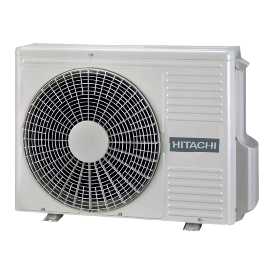
Hitachi RAS-4HVRP2E Service Manual (340 pages)
Brand:
Hitachi
| Category:
Air Conditioner
| Size: 25 MB
Table of Contents
Table of Contents
5
Introduction
14
Applied Symbols
15
Norms and Regulations
15
Product Guide
16
Classification of Outdoor Unit Models
16
Classification of Indoor Unit Models
16
Product Line-Up: Outdoor Units
17
Outdoor Unit Accessory Code List
18
Product Line-Up: Indoor Units
19
Product Line-Up: KPI Energy Recovery Unit
23
Product Line-Up: DX-Interface
23
Product Line-Up: Econofresh
23
Multi-Kits
24
Individual Remote Controls
24
Receiver Kit for Combination with Wireless Remote Control Switch
25
Centralised Remote Controls
26
Building Air Conditioning Controls
26
Control Support Devices
27
Gateways for Building Management Systems (BMS)
27
Control Accessories
28
Optional Parts and Installation for RAS-3HVRC2
30
Air Flow Guide AG-264
30
Wind Guard WSP-264
31
Snow Protection Hood
32
Air Discharge Hood
32
Rear Suction Hood
33
Left Suction Hood
34
Assembly of Snow Protection Hood
35
Optional Parts and Installation RAS-(4-6)H(V)(R/N)(C/P)2E
36
Air Flow Guide AG-335A
36
Wind Guard WSP-335A
37
Snow Protection Hood
38
Air Discharge Hood
38
Rear Suction Hood
39
Left Suction Hood
40
Assembly of Snow Protection Hood
41
Piping Work and Refrigerant Charge
43
General Notes before Performing Pipe Work
44
Piping Materials
44
Three Principles on Refrigerant Piping Work
46
Suspension of Refrigerant Piping
46
Brazing Work
47
Piping Connection for Outdoor Unit
48
Ras-3Hvrc2
48
Ras-(4-6)H(V)(R/N)(C/P)2E
49
Outdoor Unit Stop Valve
52
Piping System for Header Branch
54
Refrigerant Piping Length
54
Refrigerant Piping Range
54
Maximum Lenght of Refrigerant Piping
55
Combinations of Piping Size and Piping Length
56
Refrigerant Piping Size and Multikit/Distributor
56
System Installation
58
Refrigerant Charge
61
Caution of the Pressure by Check Joint
62
Refrigerant Charge Quantity
62
Refrigerant Charge before Shipment (W (Kg))
63
Calculation Method for the Additional Refrigerant Charge
63
Caution in Case of Refrigerant Leakage
65
Maximum Permitted Concentration of Hydrofluorocarbon (HFC)
65
Calculation of Refrigerant Concentration
65
Countermeasure for R410A Refrigerant Leakage
66
Drain Piping
67
Drain Discharging Boss
67
Electrical and Control Settings
69
Led's Indication
70
General Check
70
General Notes
70
Electrical Wiring Connection for the Outdoor Unit
71
Electrical Settings
72
Outdoor and Indoor Unit Electrical Wiring
72
Wire Size
73
Electrical Wiring Diagrams
75
Ras-3Hvrc2
75
RAS-(4-6)HV(R/N)(C/P)2E (1~ 230V 50Hz)
77
RAS-(4-6)HV(R/N)(C/P)2E (3N~ 400V 50Hz)
79
Control System
81
Device Control System
82
Ras-3Hvrc2
82
Ras-(4-6)H(V)(R/N)(C/P)2E
83
Outline of the Control System
84
Outdoor Units Printed Circuit Board (PCB)
86
Ras-3Hvrc2
86
Ras-(4-6)H(V)(R/N)(P/C)2E
87
Ras-(4-6)Hv(R/N)(C/P)2E (Pcb1)
87
Ras-(4-6)H(R/N)(C/P)2E (Pcb)
88
Protection Control
89
Protection Control Code on 7-Segment Display
89
Activating Condition of Protection Control Code
90
Control and Safety Devices
95
Standard Operation Sequence RAS-3HVRC2 and RAS-(4-6)H(V)(R/N)(C/P)2E
96
Cooling Operation
96
Dry Operation
98
Heating Operation
100
Defrost Operation RAS-3HVRC2
102
Defrost Operation RAS-(4-6)H(V)(R/N)(C/P)2E
103
Freezing Protection During Cooling Process or Dry Operation
105
Standard Control Functions
105
Prevention Control for Excessively High Discharge Gas Temperature
106
Optional Functions
107
External Input and Output Setting
108
Function Setting
108
Check Mode
108
Menu Mode Accessing (by 7-Segment Display)
108
Ras-3Hvrc2
108
External Input and Output Setting (by 7-Segment Display)
109
Available Control Functions
109
Setting of External Input and Output
110
Optional External Output Signals
110
Available Ports
111
Available Output Signals
112
Function Setting (by 7-Segment Display)
112
Sequence of the Function Setting
112
Function Setting
114
Circulator Function at Heating Thermo
117
Circulator Function at Heating Thermo-OFF (FA)
117
Night-Shift (Low Noise)(Ni)
117
Cancellation of the Outdoor Ambient Temperature Limit (GS)
118
Change of Defrost Condition (Jo)
119
Change the Opening Degree of the Expansion Valve (Si)
120
Priority Capacity Mode Setting (Nu)
120
Priority Cooling Capacity Mode (Hc)
120
Priority Heating Capacity Mode (Hh)
120
Slo Defrost Setting (Bj)
120
Change of Heating Thermo-OFF Opening Degree of the Expansion Valve (So)
121
Heating Start Opening Degree Change (CI)
121
Low Noise Setting (Db)
121
Demand Function Setting (De)
122
Cold Draft Protection (Fb)
123
Forced Stop When Defrosting Is Restored (Ds)
123
Wave Function Setting (UE)
123
Alternate Defrost Mode (F5)
124
Defrost
124
Intermittent Operation of Outdoor Fan (F1)
124
Cancellation of Defrost at Absence Judgement (F9)
125
Change Forced Stoppage Status (FE)
125
Check Mode
126
External Input and Output Setting
126
Function Setting
126
Menu Mode Accessing (by 7-Segment Display)
126
Ras-(4-6)H(V)(R/N)(C/P)2E
126
Available Control Functions
127
External Input and Output Setting (by 7-Segment Display)
127
Setting of External Input and Output
128
External Input Function Setting
129
External Output Function Setting
131
Function Setting (by 7-Segment Display)
132
Sequence of the Function Setting
132
Demand Function Setting
133
Indoor Expansion Valve Opening
133
Indoor Expansion Valve Operating
133
Low Noise Setting
133
Protection of Decrease in Outlet
133
Slo (Fan Speed)Defrost Setting
133
Temperature for Cooling
133
Function Setting
134
Circulator Function at Heating Thermo
137
Circulator Function at Heating Thermo-OFF (FA)
137
Night-Shift (Low Noise)
137
Night-Shift (Low Noise)(Ni)
137
Cancellation of Outdoor Ambient Temperature Limit
138
Cancellation of the Outdoor Ambient Temperature Limit (GS)
138
Defrost for Cold Area
139
Defrost for Cold Area (Jo)
139
Priority Capacity Mode Setting (Nu)
139
Slo Defrost Setting (Bj)
139
Demand Function Setting
140
Demand Function Setting (De)
140
Low Noise Setting (Db)
140
Cold Draft Protection
141
Cold Draft Protection (Fb)
141
Outlet Temperature (DOAS)
141
Wave Function Setting
141
Wave Function Setting (UE)
141
Outdoor Unit Capacity Control
142
Power Saving Function from Wired Controller
142
Power Saving Guide
142
Intermittent Control Function
143
Rotation Control Function
143
Operation Noise Reduction Schedule Function
144
Power Consumption Display Function
144
Power Saving Schedule Function
144
Commissioning
145
Preliminary Checks
146
Before the Test Run
147
Test Run Using the PC-ARFP1E Remote Control Switch (Example)
148
Test Run from the Outdoor Unit
150
Checking at Test Run
152
Refrigerant Cycle Checklist
153
Test Run Check List
156
Electrical Checks of Main Parts
157
Inverter
158
Ras-(4-6)Hv(R/N)(C/P)2E
158
Ras-(4-6)H(R/N)(C/P)2E
160
Specifications of Inverter
162
Inverter Time Chart
164
Protective Function
164
Overload Control
166
Thermistor
167
Thermistors for RAS-3HVRC2
167
Thermistors for RAS-(4-6)H(V)(R/N)(C/P)2E
168
Electronic Expansion Valve
171
High Pressure Protection Device
172
Ras-(4-6)H(V)(R/N)(C/P)2E
172
Ras-3Hvrc2
172
Noise Filter (NF)
173
Ras-(4-6)H(R/N)(C/P)2E
174
Ras-(4-6)Hv(R/N)(C/P)2E
174
Ras-3Hvrc2
174
Reactor (DCL)
174
Rotary Compressor
175
Servicing
177
Safety Introduction
178
Ras-3Hvrc2
179
Removing the
179
Removing the Pipe Cover
179
Removing the Outdoor Fan
180
Removing the Compressor
181
Removing the 4-Way Valve Coil
183
Removing the High Pressure Switch and Pressure Switch for Control
183
Removing the Electrical Box
184
Removing the Electronic Expansion Valve Coil
184
Removing Display PCB
185
Removing Other Electrical Components
185
Ras-(4-6)H(V)(R/N)(C/P)2E
186
Remove Outlet Grille
186
Removing Service Cover
186
Removing Upper Cover
186
Removing Bottom Service Cover and Rear Cover
187
Removing Outdoor Fan Motor
187
Removing Electrical Box
188
Removing the Compressor
191
Removing the High Pressure Switch and Pressure Switch for Control
195
Removing 4-Way Valve Coil
197
Removing Electronic Expansion Valve Coil
197
Removing 4-Way Valve
198
Removing Solenoid Valve Coil (SVA)
198
Removing Electronic Expansion Valve
199
Removing Solenoid Valve
200
Disassembly / Assembly the Electrical Components for RAS-(4-6)HV(R/N)(C/P)2E
201
Disassembly / Assembly Electrical Components for RAS-(4-6)H(R/N)(C/P)2E
206
Removing Pipe Thermistors
211
Troubleshooting
213
Initial Troubleshooting
215
Power Supply Failure to the Indoor Unit and the Remote Control Switch (PC-ARFP1E)
215
Ras-3Hvrc2
215
Simple Checking Procedure by Means of the 7-Segment Display
215
Abnormal Operation of the Devices
216
Checking the Electrical Wires and the Power Source
219
Ras-(4-6)H(V)(R/N)(C/P)2E
219
Checking by 7-Segment Display
220
Failure of the Power Supply to Indoor Units and the Remote Control Switch
223
Abnormal Transmission between Remote Control Switch and Indoor Unit
224
Abnormal Operation of the Devices
225
Alarm Codes for the Outdoor Units
236
Ras-3Hvrc2
236
Troubleshooting Procedure
236
Troubleshooting by Alarm Code
238
Alarm Codes of Wired Controller
262
Ras-(4-6)H(V)(R/N)(C/P)2E
262
Troubleshooting by Alarm Code
265
Check Mode Display by Unit Controller
298
Ras-3Hvrc2
298
Troubleshooting in Check Mode
298
Troubleshooting Using the 7 Segment Display (Outdoor Unit)
298
Ras-(4-6)H(V)(R/N)(C/P)2E
303
Troubleshooting by Using the 7-Segment Display
303
Checking Procedure for Main Parts
310
Checking Procedure for the PCB
310
Ras-3Hvrc2
310
Checking Procedeure for the DC Fan Motor
311
Checking Procedure for the Electronic Expansion Valve for Indoor and Outdoor Units
312
Checking Procedure for Other Parts
313
Checking Procedure for the Inverter PCB
315
Checking Procedure for the Compressor
316
Location of Print Circuit Boards (Pcbs)
318
Purpose
318
RSW, Dsws and Leds Functions RAS-(4-6)HV(R/N)(C/P)2E
318
Location of Print Circuit Boards (Pcbs)
321
Purpose
321
RSW, Dsws and Leds Functions RAS-(4-6)H(R/N)(C/P)2E
321
Maintenance Notes
325
Checking the Power Source and the Wiring Connection
326
General Notes
326
Insufficient Cooling Performance When a Long Piping Is Applied
326
Abnormally High Operation Sound (in the Ceiling Type Indoor Unit)
327
Alarm Code "31
327
Not Cooling Well Due to Insufficient Installation Space for the Outdoor Unit
327
Maintenance Work
328
Service and Maintenance Record
329
Service and Maintenance Record Using the 7-Segment Display
330
Information of Cause Code of Alarm
332
Information of Cause Code of Alarm Record
332
Information of Indoor Unit
332
Ras-3Hvrc2
333
Service and Maintenance Table through the Remote Control Switch
333
Ras-(4-6)(V)(R/N)(C/P)2E
335
Refrigerant Collection Method
336
Refrigerant Collection Method When Replacing the Parts of Outdoor Unit
336
Refrigerant Collection Method When Replacing Indoor Unit
338
Advertisement
Hitachi RAS-4HVRP2E Installation & Operation Manual (275 pages)
Brand:
Hitachi
| Category:
Air Conditioner
| Size: 27 MB
Table of Contents
Table of Contents
7
General Information
14
Safety
14
Applied Symbols
15
Product Guide
16
Product Line-Up: Indoor Units
16
RCI and RCIM Indoor Units
16
RCD and RPC Indoor Units
17
RPI Indoor Units
18
RPK, RPF and RPFI Indoor Units
19
Product Line-Up: Outdoor Units
20
UTOPIA IVX X Series
20
UTOPIA Series
20
UTOPIA IVX Series
21
UTOPIA RASC Series
21
SET FREE Mini Series
21
SET FREE Standard FS(X)NSE(1) Series
22
SET FREE High Efficiency FS(X)NPE(1) Series
26
Classification of Indoor Units Model
29
Classification of UTOPIA Outdoor Unit Models
29
UTOPIA Series
29
UTOPIA RASC Series
29
Classification of SET FREE Outdoor Unit Models and CH-Box Modules
30
SET FREE Mini Series
30
SET FREE Standard FS(X)NSE(1) Series
30
SET FREE High Efficiency FS(X)NPE(1) Series
30
Box
31
Name of Parts and General Dimensions
32
Indoor Units
32
Rci-(1.0-6.0)Fsr
32
Rcim-(0.4-2.5)Fsre
33
Rcd-(0.8-3.0)Fsr
34
Rcd-(4.0-6.0)Fsr
35
Rpc-(1.5-6.0)Fsr
36
Rpil-(0.4-1.5)Fsre
37
Rpi-(1.5/2.0)Fsre
38
Rpi-(2.5-6.0)Fsre
39
Rpih-(4.0-6.0)Fsre
40
RPI-(8.0/10.0)FSN3E(-F)
41
RPI-(16.0/20.0)FSN3PE(-F)
42
Rpk-(0.4-4.0)Fsr(H)M
43
Rpf-(1.0-2.5)Fsn2E
44
Rpfi-(1.0-2.5)Fsn2E
45
Outdoor Units
46
Ras-3Hvrc2
46
Ras-(4-6)H(V)(R/N)(C/P)2E
47
Ras-(4-6)(X)(V)Np1E
48
Ras-(8-10)Xhnpe / Ras-(8-10)Hnce
49
Ras-12Hnc
50
Rasc-(4-6)Hnpe
51
Rasc-(8/10)Hnpe
52
Ras-(4-6)Fsvnme
53
Ras-(4-6)Fsnme
54
Ras-(8-12)Fsxnme
55
RAS-FSNSE1 (Standard Series)
56
RAS-FSXNSE(1) (Standard Series)
60
RAS-FSNPE1 (High Efficiency Series)
64
RAS-FSXNPE(1) (High Efficiency Series)
67
Remote Controller
70
Automatic Controls
70
Refrigerant Cycle
71
Indoor Units
71
All Models Except RPK-FSRHM
71
RPK-FSRHM Only
72
Outdoor Units: UTOPIA Series
72
General Notes
72
UTOPIA IVX X Series - RAS-(4-10)XH(V)NP(1)E
73
UTOPIA Series - RAS-(3-6)H(V)R(C/P)2(E)
75
UTOPIA IVX Series - RAS-(8-12)-HNC(E)
77
Outdoor Units: CENTRIFUGAL VRF Series
79
Rasc-(4-6)Hnpe
79
Rasc-(8/10)Hnpe
80
Outdoor Units: SET FREE Mini Series
81
Ras-(4-6)Fs(V)Nme
81
Ras-(8-12)Fsxnme
82
Outdoor Units: SET FREE FS(X)N(S/P)E(1)
83
Standard Type - RAS-(8-24)FSNSE1
83
Standard Type - RAS-(8-24)FSXNSE(1)
87
High Efficiency Type - RAS-(5-18)FSNPE1
91
High Efficiency Type - RAS-(5-18)FSXNPE(1)
94
Box
97
Ap160Ssx, Ch-Ap280Ssx
97
Ap04Mssx
97
Ap08Mssx
98
Ap12Mssx
98
Ap16Mssx
99
Refrigerant Piping
100
Selection of the Copper Pipes
100
Three Principles on Work with Refrigerant Pipes
100
Flared Pipes
101
Selection of the Connection with Flare Fitting
101
Dimensions of Flared Pipe
101
Flared Connection Mounting
101
General Instructions on the Installation of Refrigerant Pipes
103
Preparing Copper Refrigeration Pipes
103
Cutting Copper Refrigeration Pipes
104
Bending Copper Pipes
104
Brazing Copper Refrigerant Pipes
104
Refrigerant Pipe Insulation
105
Suspension of Refrigerant Piping
106
Line Branch and Header Branch Installation
106
Piping Connection for Outdoor Unit
107
Utopia Ras-(4-6)H(V)(R/N)(C/P)2E
107
Rasc-(8/10)Hnpe
110
SET FREE Mini SERIES
111
Set Free Fsxnse / Fsxnpe Series
115
Stop Valve
117
Gas Valve
117
Set Free Fs(X)Nse1 / Fs(X)Npe1
125
Refrigerant Piping Lenght
135
UTOPIA Series
135
Refrigerant Piping Length
135
Piping System for Header Branch
135
Piping System for Line Branch (UTOPIA IVX Only)
137
Combinations of Piping Size and Piping Length
138
Refrigerant Piping Size and Multi-Kit/Distributor
139
UTOPIA CENTRIFUGAL VRF Series
141
Refrigerant Piping Length
141
Piping System (Header Branch Installation)
141
Piping System (Line Branch Installation)
143
Combinations of Piping Size and Piping Length
144
Refrigerant Piping Size and Multi-Kit/Distributor Selection
144
SET FREE Mini Series
147
RAS-(4-6)FS(V)NME Pipe Working Conditions
147
RAS-(8-12)FSXNME Pipe Working Conditions
148
Pipe Branching Restrictions (Installation with Main Piping Branch)
150
SET FREE FS(X)N(S/P)E(1) Series
152
Connection Kit Selection
152
Example of Installation
153
Pipe Working Conditions
154
For Heat Recovery Systems (3 Pipes)
155
Connection of Refrigerant Pipes for Heat Pump System (2 Pipes)
157
Size of Pipes (Ø MM) for Heat Pump Systems (2 Pipes)
157
Connection of Refrigerant Pipes for Heat Recovery (3 Pipes)
167
Size of Pipes (Ø MM) for Heat Recovery Systems (3 Pipes)
168
Pipe Branching Restrictions (Installation with Main Piping Branch)
178
Precautions for the Installation of the Outdoor Unit
179
Drain Piping
185
General Information
185
Rcim-(0.4-2.5)Fsre
186
Drain Pipe Connection
186
Rpi(L/H)-(0.4-6.0)Fsre
190
Checking with the Standard Drainage (Drain Pump)
190
Checking in Case of Drainage for Gravity (Only for RPIL-FSRE Models)
190
Drain Pipe Connection
190
Rasc-(4-10)Hnpe
195
Provision Regarding Installation Place
195
Drain Pipe Location
195
Drain Pipe Connection
195
Utopia Ras-(4-6)H(V)(R(P/C)2E
196
Drain Discharging Boss
196
Connecting Procedure for DBS-26
196
Set Free Ras-(5-96)Fsxn(S/P)E
197
Installation Position of the Optional Drainage Kit DBS-TP10A
198
Electrical Wiring
199
Settings of DIP Switches
200
Indoor Units
200
Setting of DIP Switches for Outdoor Unit RAS-(4-6)HV(R/N)(C/P)2E
204
Setting of DIP Switches for Outdoor Unit RAS-(4-10)XH(V)NP(1)E and RAS-(8-10)HNCE
206
Setting of DIP Switches for Outdoor Unit RAS-12HNCE
208
Setting and Function of DIP and RSW Switches for RASC Units
210
Setting of DIP Switches for Outdoor Unit SET FREE FS(X)N(S/P)E(1)
214
Common Wiring
218
Electrical Wiring between Indoor Unit and Outdoor Unit
218
Outdoor and Indoor Units Layouts for UTOPIA
219
Outdoor and Indoor Units Layouts for SET FREE
221
Connection Diagram of SET FREE and RPI-(16.0/20.0)FSN3PE(-F) Indoor Unit
222
Removing / Assembling Electrical Box (for RPI(L/H)FSRE Series
223
Installation Conditions for Rpi(L/H)-Fsre and Rcim(0.4-2.5)Fsre Units
226
Duct and Suction Air Filter Installation for RPI(L/H)
226
Field Supply Duct Installation
226
Efficient Use of Cooling and Heating for RCI/RCIM
228
Fan Performace Curves
229
Rpi(L/H)Fsre
229
Static Pressure Setting
231
Rasc-(4-10)Hnpe
232
Setting of the Fan Performance Curves
234
Before Operation
235
Efficient Use of Indoor Unit
235
Commissioning
235
Utopia Ras-(4-6)H(V)(R/N)(C/P)2E
235
Set Free Fs(X)Nse(1) / Fs(X)Npe(1) Series
236
Preliminary Checks
236
Carry out the Test Run
237
Vacuum Pumping
238
UTOPIA Vacuum Layout Example
239
SET FREE Heat Recovery Vacuum Layout Example
240
Charging Work
240
All Units Except SET FREE FS(X)NSE(1) / FS(X)NPE(1) Series
240
For SET FREE FS(X)NSE(1) / FS(X)NPE(1) Series
241
UTOPIA Charging Work Example
243
SET FREE Mini Heat Recovery System Layout Example
243
SET FREE Heat Pump System Layout Example
244
SET FREE Heat Recovery System Layout Example
244
Refrigerant Pump down
245
UTOPIA Refrigerant Pump down Example
245
SET FREE Heat Recovery Refrigerant Pump down Example
246
Link II System
246
Specifications
246
System Installation DSW Setting
247
F Outdoor Unit
247
Indoor Units
247
Outdoor Unit
247
Test Run from Outdoor Unit Side
248
UTOPIA IVX, UTOPIA RASC, SET FREE Mini (4-6 HP)
248
SET FREE Mini (8-12HP)
249
Test Run Check List
250
Troubleshooting
251
ON-Screen Display During Abnormal Operation
251
Main Alarm Codes
252
Outdoor Unit
252
Outdoor Unit
253
SET FREE CH-Box
255
KPI Series 4 and DX-Interface Series 2
256
Maintenance
257
General Maintenance Work
257
Optional Parts for Utopia Series
259
Asigned Models and Quantity
259
Air Flow Guide
260
254
260
Ag-335A
261
Wind Guard
262
256
262
Wsp-335A
263
Wsp-160A
264
Snow Protection Hood
265
Air Discharge Hood
265
Rear Suction Hood
267
Left Suction Hood
269
Assembly of Snow Protection Hood
271
Outdoor Unit
271
Drain Heater
273
Accessories Packed with Drain Pan Heater
273
Hitachi RAS-4HVRP2E Technical Catalogue (132 pages)
Brand:
Hitachi
| Category:
Air Conditioner
| Size: 14 MB
Table of Contents
Table of Contents
5
1 General Information
9
General Information
10
Introduction
10
Applied Symbols
11
Norms and Regulations
11
Product Guide
12
Classification of Outdoor Unit Models
12
Classification of Indoor Unit Models
12
Product Line-Up: Outdoor Units
13
Outdoor Unit Accessory Code List
14
Product Line-Up: Indoor Units
15
Product Line-Up: KPI Energy Recovery Unit
19
Product Line-Up: DX-Interface
19
Product Line-Up: Econofresh
19
Multi-Kits
20
Individual Remote Controls
20
Receiver Kit for Combination with Wireless Remote Control Switch
21
Centralised Remote Controls
22
Building Air Conditioning Controls
22
Gateways for Building Management Systems (BMS)
23
Control Support Devices
24
Control Accessories
24
2 Features and Benefits
25
Features and Benefits
26
Improvements of UTOPIA Prime / UTOPIA IVX Prime Series
26
R32 Refrigerant
26
Eco-Desing and Seasonal Efficiency
27
Eco-Design
27
Seasonal Efficiency
27
Energy Classes and Energy Label (Lot 10)
28
General Features and Benefits of the UTOPIA Prime / UTOPIA IVX Prime Series
30
Main Features
30
Selection Benefits
32
Wide Range of UTOPIA Outdoor Units
32
Wide Range of Indoor Units Combinable with UTOPIA Prime and UTOPIA IVX Prime
33
Installation Benefits
34
Start-Up Benefits
35
Automatic Start-Up Test
35
Service Verification
36
Maintenance Benefits
37
Availability of Maintenance Tools
37
Simple Maintenance
37
3 General Data
39
General Information
40
General Specifications
41
Cooling and Heating Performance
49
UTOPIA Prime Single Phase Series
49
UTOPIA IVX Prime Single Phase Series
49
UTOPIA Prime Three Phase Series
50
UTOPIA IVX Prime Three Phase Series
50
Component Data
51
Electrical Data
53
UTOPIA Series
54
4 Capacities and Selection Data
55
Combinability Range
56
Connected Number of Indoor Units
56
Connected Capacity Ratio
57
System Selection Procedure
58
Selection Procedure (Step 1)
58
Selection Procedure (Step 2)
60
Maximum Cooling Capacity
61
Maximum Heating Capacity
63
Correction Indoor Fan Speed Factor
65
Cooling
65
Heating
65
Piping Length Correction Factor
65
Lc Lh
65
Defrost Operation Correction Factor (F )
67
Correction Ratio Due to Humidity (CR)
67
Correction Factor According to Altitude
67
5 Acoustic Characteristic Curves
69
Overall Sound Level
70
Sound Pressure Curves
71
Sound Power Curves
73
6 Working Range
75
Working Range
76
Power Supply
76
Temperature Working Range
76
Special DSW Configuration for Low Ambient Temperature (-15ºC) - Only for Simultaneous Operation Mode Units (UTOPIA Prime)
77
7 General Dimensions
79
Dimensions
80
Ras-3Hvrc2
80
Ras-(4-6)H(V)(R/N)(C/P)2E
81
Service Space
82
Basic Sizes
82
Ras-3Hvrc2
83
Ras-(4-6)H(V)(R/N)(C/P)2E
85
8 Refrigerant Cycle
87
General Notes
88
Ras-3Hvrc2
88
Ras-(4-6)H(V)(R/N)(C/P)2E
89
9 Piping Work and Refrigerant Charge
91
Refrigerant Pipe Selection
92
Pipe Size Selection
92
Multikit or Distributor Selection
92
Refrigerant Piping Range
92
Refrigerant Piping Length
92
Piping System for Header Branch
93
Maximum Lenght of Refrigerant Piping
94
Combinations of Piping Size and Piping Length
96
Refrigerant Piping Size and Multikit/Distributor
96
Copper Pipes, Sizes and Connection
98
Copper Pipes and Sizes
98
Insulation
99
Refrigerant Charge Amount
100
Refrigerant Charge before Shipment (W (Kg))
100
Calculation Method for the Additional Refrigerant Charge
100
Caution in Case of Refrigerant Leakage
102
Maximum Permitted Concentration of Hydrofluorocarbon (HFC)
102
Calculation of Refrigerant Concentration
102
Countermeasure for R410A Refrigerant Leakage
103
10 Electrical Wiring
105
General Information
106
Electromagnetic Compatibility
106
Harmonics
107
General Verifications
107
DIP and RSW Switches Settings
107
Ras-3Hvrc2
107
Ras-(4-6)H(V)(R/N)(P/C)2E
110
System Wiring Diagram
113
Outdoor and Indoor Unit Electrical Wiring
113
Wire Size
114
H-LINK II System
115
Features
115
Specifications
115
DIP Switch Setting for 2, 3 and 4 Indoor Units Systems
116
Examples of the System of Connection between H-LINK and H-LINK II Units
118
Examples of H-LINK II System
119
System Control - Main Concept
121
UTOPIA Prime
121
UTOPIA IVX Prime
122
System Control Comparison
123
11 Troubleshooting
125
On-Screen Displays During Abnormal Operation
126
Alarm Codes
128
Advertisement
Hitachi RAS-4HVRP2E Installation & Operation Manual (50 pages)
Brand:
Hitachi
| Category:
Computer Hardware
| Size: 5 MB
Hitachi RAS-4HVRP2E Installation And Operation Manual (50 pages)
Brand:
Hitachi
| Category:
Air Conditioner
| Size: 5 MB
Hitachi RAS-4HVRP2E Installation & Operation Manual (50 pages)
Brand:
Hitachi
| Category:
Air Conditioner
| Size: 5 MB
Hitachi RAS-4HVRP2E Installation & Operation Manual (50 pages)
Brand:
Hitachi
| Category:
Air Conditioner
| Size: 5 MB
Hitachi RAS-4HVRP2E Installation & Operation Manual (50 pages)
Brand:
Hitachi
| Category:
Air Conditioner
| Size: 5 MB
Hitachi RAS-4HVRP2E Installation & Operation Manual (50 pages)
Brand:
Hitachi
| Category:
Air Conditioner
| Size: 5 MB
Hitachi RAS-4HVRP2E Installation & Operation Manual (50 pages)
Brand:
Hitachi
| Category:
Air Conditioner
| Size: 5 MB
Hitachi RAS-4HVRP2E Installation & Operation Manual (50 pages)
Cooling & Heating Outdoor Unit
Brand:
Hitachi
| Category:
Heat Pump
| Size: 5 MB
Advertisement
Related Products
Hitachi Utopia RAS-4HVRG
Hitachi RAS-4HVRNM2
Hitachi RAS-4HVRNME-AF
Hitachi RAS-4HVRNM1E
Hitachi RAS-4HVRNS1E
Hitachi RAS-4HVRNS3E
Hitachi RAS-4HVRNS2E
Hitachi AQUA FREE RAS-4HVRNE
Hitachi RAS-4HVRC2E
Hitachi YUTAKI S RAS-4HVRNME
Hitachi Categories
Air Conditioner
Projector
Drill
Refrigerator
TV
More Hitachi Manuals
Login
Sign In
OR
Sign in with Facebook
Sign in with Google
Upload manual
Upload from disk
Upload from URL