Sign In
Upload
Manuals
Brands
hilscher Manuals
Gateway
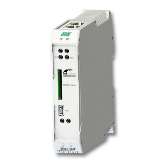
netTAP NT 151-RE-RE
hilscher netTAP NT 151-RE-RE Manuals
Manuals and User Guides for hilscher netTAP NT 151-RE-RE. We have
2
hilscher netTAP NT 151-RE-RE manuals available for free PDF download: User Manual
hilscher netTAP NT 151-RE-RE User Manual (92 pages)
Real-Time Ethernet gateway
Brand:
hilscher
| Category:
Gateway
| Size: 3 MB
Table of Contents
Table of Contents
2
Introduction
4
About this Document
4
Description of the Contents
4
Obligation to Read the Manual
4
List of Revisions
5
Table 1: List of Revisions
5
Conventions in this Document
6
Reference to Hardware, Firmware, Software and Drivers
7
Table 2: Reference to Firmware
7
Table 3: Reference to Software
8
Table 4: Reference on Device Description Files
8
Table 5: Reference to Drivers
9
Contents of the Product DVD
10
Table 6: Directory of Gateway Solutions DVD
11
Documentation Overview
12
Table 7: Basic Documentation for NT 151-RE-RE
12
Table 8: Additional Documentation for NT 151-RE-RE as PROFINET IO Controller
12
Table 9: Additional Documentation for NT 151-RE-RE as PROFINET IO Device
13
Table 10: Additional Documentation for NT 151-RE-RE as Ethercat Master
13
Table 11: Additional Documentation for NT 151-RE-RE as Ethercat Slave
13
Table 12: Additional Documentation for NT 151-RE-RE as Ethernet/Ip Scanner
14
Table 13: Additional Documentation for NT 151-RE-RE as Sercos Master
14
Legal Notes
15
Registered Trademarks
19
Safety
20
General Note
20
Intended Use
20
Personnel Qualification
20
Safety References
20
Safety Instructions to Avoid Personal Injury
21
Danger of Unsafe System Operation
21
Safety Instructions to Avoid Property Damage
21
Device Destruction by Exceeding Allowed Supply Voltage
21
Danger of Unsafe System Operation
22
Device Destruction Due to Overheating
22
Exceeding the Maximum Number of Allowed Write/Delete Accesses
22
Labeling of Safety Messages
23
Table 14: Signal Words in Safety Messages on Personal Injury
23
Table 15: Safety Signs in Messages on Personal Injury
23
Table 16: Signal Words in Safety Messages on Property Damage
23
Table 17: Safety Signs in Safety Messages on Property Damage
23
Description
24
Functionality
24
Figure 1: Data Flow Nettap NT 151-RE-RE
24
Protocol Conversions
26
Table 18: Available Protocol Conversions with Article Numbers and Firmware Names
26
Interfaces
27
Requirements
28
Device Drawings and Connectors
29
Dimensioned Drawings
29
Figure 2: Outer Dimensions of NT 151
29
Figure 3: Dimensions of Mini COMBICON Power Supply Plug
29
Positions of the Interfaces and Leds
30
Table 19: Leds and Interfaces NT 151-RE-RE
30
Table 26: APL LED
30
Device Label
31
Table 20: Protocol Abbreviations
31
Protocol Logo and LED Label Sticker
32
Figure 4: Protocol Stickers
32
Power Supply Connector
33
Table 21: Pin Assignment of 5-Pole Power Supply Socket
33
Table 22: Pin Assignment Mini Combicon Plug 5-Pole
33
Ethernet Connectors
34
USB Interface (Mini-B USB)
34
Table 23: Ethernet RJ45 Pin Assignment
34
Table 24: Pin Assignment Mini-B USB Connector (5-Pin)
34
Galvanic Isolation
35
Figure 5: Galvanic Isolation of NT 151-RE-RE
35
Mounting of Device
36
Safety Messages
36
Mounting Device Onto Top hat Rail
37
Figure 6: Mounting the Nettap Device Onto Top hat Rail
37
Removing Device from Top hat Rail
38
Figure 7: Removing the Nettap Device from Top hat Rail
38
Commissioning
39
Firmware Recovery
41
Overview
41
Using an SD Memory Card to Reset the Nettap to Its "Factory Settings
42
Figure 8: Insert SD Card
43
Using USB to Recover Firmware
44
Figure 9: Comprox Start Window
45
Figure 10: Activate Auto Refresh Function
46
Figure 11: Comprox Open USB Port Dialog Window
46
Figure 12: Contents of the Nettap Ports Displayed in Comprox
47
Figure 13: Format Flash Memory
48
Figure 14: Acknowledge Formatting Dialog
48
Figure 15: Formatting Finished Message
49
Figure 16: Download Menu
49
Figure 17: Open File Dialog
50
Figure 18: Download Status
50
Figure 19: Download Finished Message
51
Figure 20: Firmware in PORT_0
51
Using SD Memory Card to Copy Configuration Data into Spare Nettap Devices
52
Overview
52
Prerequisites
52
Step-By-Step Instructions
53
Figure 21: Login Sycon.net
53
Figure 22: Empty Project in Sycon.net
53
Figure 23: Add Nettap in Sycon.net
54
Figure 24: Device Assignment 1
55
Figure 25: Device Assignment 2
56
Figure 26: Device Assignment 3
56
Figure 27: Memory Card Management of the Nettap DTM
57
Figure 28: Insert SD Card
57
Figure 29: Memory Card Management after Inserting SD Memory Card
58
Figure 30: Memory Card Management after Backup to SD Memory Card
59
Leds
60
Overview
60
Sys Led
60
Table 25: System LED
60
Apl Led
61
Leds of the Real-Time Ethernet Systems
62
Leds PROFINET IO Controller
62
Table 27: LED States for the PROFINET IO-Controller Protocol
62
Table 28: LED State Definitions for the PROFINET IO-Controller Protocol
62
Leds PROFINET IO Device
63
Table 29: LED States for the PROFINET IO-Device Protocol
63
Table 30: LED State Definitions for the PROFINET IO-Device Protocol
63
Leds Ethercat Master
64
Table 31: LED States for the Ethercat Master(V4) Protocol
64
Table 32: LED State Definitions for the Ethercat Master(V4) Protocol
65
Leds Ethercat Slave
66
Table 33: LED States for the Ethercat Slave Protocol
66
Table 34: LED State Definitions for the Ethercat Slave Protocol
66
Leds Ethernet/Ip Scanner
67
Table 35: LED States for the Ethernet/Ip Scanner Protocol
67
Table 36: LED State Definitions for the Ethernet/Ip Scanner Protocol
68
Leds Ethernet/Ip Adapter
69
Table 37: LED States for the Ethernet/Ip Adapter Protocol
69
Table 38: LED State Definitions for the Ethernet/Ip Adapter Protocol
70
Leds Sercos Master
71
Table 39: LED States for the Sercos Master Protocol
71
Table 40: LED State Definitions for the Sercos Master Protocol
72
LED Sercos Slave
73
Leds POWERLINK Controlled Node
75
Leds Openmodbus/Tcp (Client and Server)
76
Troubleshooting
77
Technical Data
78
Technical Data Nettap NT 151-RE-RE
78
Technical Data of the Protocols
80
PROFINET IO Controller
80
PROFINET IO Device
81
Ethernet/Ip Scanner
83
Ethernet/Ip Adapter
84
Ethercat Master
84
Ethercat Slave
85
Sercos Master
85
Sercos Slave
86
POWERLINK Controlled Node
86
Open Modbus/Tcp
87
Decommissioning/Disposal
88
Putting the Device out of Operation
88
Disposal of Waste Electronic Equipment
88
List of Figures
89
List of Tables
90
Advertisement
hilscher netTAP NT 151-RE-RE User Manual (81 pages)
Real-Time Ethernet gateway
Brand:
hilscher
| Category:
Gateway
| Size: 3 MB
Table of Contents
Table of Contents
2
1 Introduction
4
About this Document
4
Description of the Contents
4
Obligation to Read the Manual
4
List of Revisions
4
Table 1: List of Revisions
4
Conventions in this Document
5
Reference to Hardware, Firmware, Software and Drivers
6
Table 2: Reference to Firmware
6
Table 3: Reference to Software
7
Table 4: Reference on Device Description Files
7
Table 5: Reference to Drivers
7
Contents of the Product DVD
8
Table 6: Directory of Gateway Solutions DVD
9
Documentation Overview
10
Table 7: Basic Documentation for NT 151RERE
10
Table 8: Additional Documentation for NT 151RERE as PROFINET IO Controller
10
Table 9: Additional Documentation for NT 151RERE as PROFINET IO Device
11
Table 10: Additional Documentation for NT 151RERE as Ethercat Master
11
Table 11: Additional Documentation for NT 151RERE as Ethercat Slave
11
Table 12: Additional Documentation for NT 151RERE as Ethernet/Ip Scanner
12
Table 13: Additional Documentation for NT 151RERE as Sercos Master
12
Legal Notes
13
Copyright
13
Important Notes
13
Exclusion of Liability
14
Warranty
14
Export Regulations
15
Registered Trademarks
15
2 Safety
16
General Note
16
Intended Use
16
Personnel Qualification
16
References Safety
16
Safety Instructions to Avoid Personal Injury
17
Danger of Unsafe System Operation
17
Safety Instructions to Avoid Property Damage
17
Device Destruction by Exceeding Allowed Supply Voltage
17
Danger of Unsafe System Operation
18
Device Destruction Due to Overheating
18
Labeling of Safety Messages
19
Table 14: Signal Words in Safety Messages on Personal Injury
19
Table 15: Safety Signs in Messages on Personal Injury
19
Table 16: Signal Words in Safety Messages on Property Damage
19
Table 17: Safety Signs in Safety Messages on Property Damage
19
3 Description
20
Functionality
20
Figure 1: Data Flow Nettap NT 151RERE
20
Protocol Conversions
22
Interfaces
22
Table 18: Available Protocol Conversions with Article Numbers and Firmware Names
22
4 Requirements
23
5 Device Drawings and Connectors
24
Dimensioned Drawings
24
Figure 2: Outer Dimensions of NT 151RERE
24
Figure 3: Dimensions of Mini COMBICON Power Supply Plug
24
Positions of the Interfaces and Leds
25
Table 19: Leds and Interfaces NT 151RERE
25
Device Label
26
Protocol Logo and LED Label Sticker
27
Figure 4: Protocol Stickers
27
Power Supply Connector
28
Ethernet Connectors
28
Table 20: Pin Assignment of 5Pole Power Supply Socket
28
Table 21: Pin Assignment Mini Combicon Plug 5Pole
28
USB Interface (Minib USB)
29
Table 22: Ethernet RJ45 Pin Assignment
29
Table 23: Pin Assignment Minib USB Connector (5Pin)
29
Galvanic Isolation
30
Figure 5: Galvanic Isolation of NT 151RERE
30
6 Mounting of Device
31
Safety Messages
31
Mounting Device Onto Top hat Rail
32
Figure 6: Mounting the Nettap Device Onto Top hat Rail
32
Removing Device from Top hat Rail
33
Figure 7: Removing the Nettap Device from Top hat Rail
33
7 Commissioning
34
8 Firmware Recovery
36
Overview
36
Using an SD Memory Card to Reset the Nettap to Its "Factory Settings
37
Figure 8: Insert SD Card
38
Using USB to Recover Firmware
39
Figure 9: Comprox Start Window
40
Figure 10: Activate Auto Refresh Function
41
Figure 11: Comprox Open USB Port Dialog Window
41
Figure 12: Contents of the Nettap Ports Displayed in Comprox
42
Figure 13: Format Flash Memory
43
Figure 14: Acknowledge Formatting Dialog
43
Figure 15: Formatting Finished Message
44
Figure 16: Download Menu
44
Figure 17: Open File Dialog
45
Figure 18: Download Status
45
Figure 19: Download Finished Message
46
Figure 20: Firmware in PORT_0
46
9 Using SD Memory Card to Copy Configuration Data into Spare Nettap Devices
47
Overview
47
Prerequisites
47
Stepbystep Instructions
48
Figure 21: Login Sycon.net
48
Figure 22: Empty Project in Sycon.net
48
Figure 23: Sycon.net_Sd_Karte1
49
Figure 24: Device Assignment 1
50
Figure 25: Device Assignment 2
51
Figure 26: Device Assignment 3
51
Figure 27: Memory Card Management of the Nettap DTM
52
Figure 28: Insert SD Card
52
Figure 29: Memory Card Management after Inserting SD Memory Card
53
Figure 30: Memory Card Management after Backup to SD Memory Card
54
10 Leds
55
Sys Led
55
Table 24: System LED
55
Apl Led
56
Table 25: APL LED
56
Leds of the Realtime Ethernet Systems
57
Leds PROFINET IO Controller
57
Table 26: LED States for the PROFINET Iocontroller Protocol
57
Table 27: LED State Definitions for the PROFINET Iocontroller Protocol
57
Leds PROFINET IO Device
58
Table 28: LED States for the PROFINET Iodevice Protocol
58
Table 29: LED State Definitions for the PROFINET Iodevice Protocol
58
Leds Ethercat Master
59
Table 30: LED States for the Ethercat Master(V3) Protocol
59
Table 31: LED State Definitions for the Ethercat Master(V3) Protocol
59
Leds Ethercat Slave
60
Table 32: LED States for the Ethercat Slave Protocol
60
Table 33: LED State Definitions for the Ethercat Slave Protocol
60
Leds Ethernet/Ip Scanner
61
Table 34: LED States for the Ethernet/Ip Scanner Protocol
61
Table 35: LED State Definitions for the Ethernet/Ip Scanner Protocol
61
Leds Ethernet/Ip Adapter
62
Table 36: LED States for the Ethernet/Ip Adapter Protocol
62
Table 37: LED State Definitions for the Ethernet/Ip Adapter Protocol
62
Leds Sercos Master
63
Table 38: LED States for the Sercos Master Protocol
63
Table 39: LED State Definitions for the Sercos Master Protocol
64
LED Sercos Slave
65
Table 40: LED States for the Sercos Slave Protocol
65
Table 41: LED State Definitions for the Sercos Slave Protocol
66
11 Troubleshooting
67
Table 42: Nettap NT 151RERE Troubleshooting by LED
67
12 Technical Data
68
Technical Data Nettap NT 151RERE
68
Table 43: Technical Data Nettap NT 151RERE
69
Technical Data of the Protocols
70
PROFINET IO Controller
70
Table 44: Technical Data PROFINET IO Controller Protocol
70
PROFINET IO Device
71
Table 45: Technical Data PROFINET IO RT IRT Device Protocol
72
Ethernet/Ip Scanner
73
Table 46: Technical Data Ethernet/Ip Scanner (Master) Protocol
73
Ethernet/Ip Adapter
74
Ethercat Master
74
Table 47: Technical Data Ethernet/Ip Adapter (Slave) Protocol
74
Table 48: Technical Data Ethercat Master Protocol
74
Ethercat Slave
75
Sercos Master
75
Table 49: Technical Data Ethercat Slave Protocol
75
Table 50: Technical Daten Sercos Master Protocol
75
Sercos Slave
76
Table 51: Technical Data Sercos Slave Protocol
76
13 Decommissioning/Disposal
77
Putting the Device out of Operation
77
Disposal of Waste Electronic Equipment
77
List of Figures
78
Contacts
81
Advertisement
Related Products
hilscher netTAP NT 151-CCIES-RE
hilscher netTAP NT 50 Series
hilscher netTAP NT 50-CO-EN
hilscher netTAP NT 50-CO-RS
hilscher netTAP NT 50-CC-EN
hilscher netTAP NT 50-CC-RS
hilscher netTAP NT 50-DN-EN
hilscher netTAP NT 50-DN-RS
hilscher netTAP NT 50-DP-EN
hilscher netTAP NT 50-DP-RS
hilscher Categories
Gateway
Computer Hardware
Network Hardware
Motherboard
Control Unit
More hilscher Manuals
Login
Sign In
OR
Sign in with Facebook
Sign in with Google
Upload manual
Upload from disk
Upload from URL