Sign In
Upload
Manuals
Brands
Garmin Manuals
GPS
GTR 200
Garmin GTR 200 Manuals
Manuals and User Guides for Garmin GTR 200. We have
5
Garmin GTR 200 manuals available for free PDF download: Installation Manual, Pilot's Manual
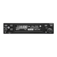
Garmin GTR 200 Installation Manual (88 pages)
COM Transceiver
Brand:
Garmin
| Category:
Transceiver
| Size: 2.67 MB
Table of Contents
Table of Contents
5
Paragraph Page
6
Section 1 General Description
10
Section 1 General Description
10
Introduction
10
Equipment Description
10
Table 1-1 Available Units
10
Technical Specifications
11
Table 1-2 Physical Characteristics
11
Table 1-3 General Specifications
11
Table 1-4 Display Specifications
12
Table 1-5 COM Transmitter Specifications
12
Table 1-6 COM Receiver Specifications
13
Certification
14
Reference Documents
14
Table 1-7 FCC Grant of Equipment Authorization
14
Table 1-8 Reference Documents
14
Section 2 Installation Overview
15
Section 2 Installation Overview
15
Introduction
15
Unit Configurations
15
Available Accessories
15
Table 2-1 Catalog Part Numbers
15
Table 2-2 Standard Kit Accessories
15
Installation Considerations
16
Table 2-4 Optional Accessories
16
Antenna Considerations
17
Mounting Considerations
19
Cabling and Wiring
19
Section 2 Installation Overview
20
Figure 2-1 CAN Bus Configuration
20
Air Circulation and Cooling
21
Compass Safe Distance
21
Section 3 Installation Procedures
22
Section 3 Installation Procedures
22
Unpacking the Unit
22
Wiring Harness Installation
22
Table 3-1 Recommended Crimp Tools (or Equivalent)
22
Table 3-2 Socket Contact Part Numbers
22
Backshell Assembly
23
Mounting Requirements
23
Antenna Installation and Connections
24
Section 3 Installation Procedures
25
Post Installation Configuration and Checkout Procedures
25
Figure 3-1 GTR 200/200B Front Panel
25
Figure 3-2 Configuration Mode Home Page
26
Table 3-3 Configuration Default Settings
27
Figure 3-3 COM Setup Page
28
Figure 3-4 ICS Sidetone Selection
28
Table 3-4 COM Setup Page Selections
28
Figure 3-5 MON Swap Selection
29
Figure 3-6 Audio Setup Page (aux and Music Disabled)
30
Figure 3-7 Audio Setup Page (aux and Music Enabled)
30
Table 3-5 Audio Setup Page Selections
30
Figure 3-8 Softkey Setup Page
31
Table 3-6 Softkey Setup Page Selections
31
Figure 3-9 Discrete Setup Page
32
Table 3-7 Discrete Setup Page Selections
32
Figure 3-10 Lighting Setup Page
33
Table 3-8 Lighting Setup Page Selections
33
Figure 3-11 Lighting Graph
34
Figure 3-12 RS-232 Status Page
34
Figure 3-13 Headset Tests Page
35
Figure 3-14 COM Tests Page
36
Figure 3-15 Audio Tests Page
37
Table 3-9 Audio Tests Source Selections
37
Table 3-10 Discrete Inputs
38
Table 3-11 TX Interlock Connections
39
Unit Software
41
Figure 3-16 about Page
41
Figure 3-17 Software Update Page
41
Figure 3-18 Micro SD Insertion
42
Figure 3-19 Software Update Page - Scanning Card
42
Figure 3-20 Software Update Page - no Update Found
43
Figure 3-21 Software Update Page - Update Software
43
Figure 3-22 Software Update Page - Preparing Update
43
Figure 3-23 Software Update Page - Unit will Reboot
43
Disabling Bluetooth
44
Continued Airworthiness
44
Section 4 Connector Pinout Information
45
Section 4 Connector Pinout Information
45
Section 4 Connector Pinout Information
45
Pin Function List
45
Figure 4-1 J2001 Looking at Rear of Unit
45
Table 4-1 J2001 Connector
45
Power
46
Lighting Bus
46
CAN Bus
47
Unit ID
47
Figure 4-2 CAN Bus Termination for GTR 200/200B
47
Serial Data - RS-232
48
MIC Audio
48
Aux Mono Audio
49
Headset Audio
49
Music Inputs
49
Receiver Audio
50
Pilot/Copilot PTT Inputs
50
TX Interlock
50
Discrete Inputs
51
Appendix A Shield Block Connector Installation Instructions
52
Appendix A Shield Block Connector Installation Instructions
52
Shield Block Installation Parts
52
Table A-1 Parts Not Supplied for a Shield Block Installation (Figure
52
Appendix A Shield Block Connector Installation Instructions
53
Figure A-1 Shield Block Install Onto a Backshell
53
Shield Termination Technique - Method A.1 (Standard
54
Figure A-2 Method A.1 for Shield Termination
54
Table A-2 Shielded Cable Preparations for Garmin Connectors
54
Figure A-3 Insulation/Contact Clearance
56
Shield Termination Technique - Method A.2 (Daisy Chain
58
Shield Termination - Method B.1 (Quick Term
58
Figure A-4 Method A.2 (Daisy Chain) for Shield Termination
58
Figure A-5 Method B.1 (Quick Term) for Shield Termination
59
Shield Termination-Method B.2 (Daisy Chain-Quick Term
60
Figure A-6 Method B.2 (Daisy Chain-Quick Term) for Shield Termination
60
Table A-3 Shielded Cable Preparations - (Quick Term
60
Daisy Chain between Methods a and B
61
Splicing Signal Wires
61
Figure A-7 Daisy Chain between Methods a and B
61
Figure A-8 D-Sub Spliced Signal Wire Illustration
62
Appendix B Serial Interface Specifications
63
Electrical Interface
63
Message Formats
63
Appendix C Outline and Installation Drawings
75
Figure C-1 GTR 200/200B Outline Drawing
75
Figure C-2 GTR 200/200B Assembly Drawing
76
Figure C-3 GTR 200/200B Installation Drawing
77
Appendix C Outline and Installation Drawings
78
Figure C-4 GTR 200/200B Panel Cutout Drawing
78
Appendix D Interconnect Examples
79
Figure D-1 GTR 200/200B Interconnect Example Notes
79
Appendix D Interconnect Examples
80
Figure D-2 GTR 200/200B- Power & Ground/Intercom/Gdu 37X/46X CAN Bus Interconnect Example
80
Figure D-3 GTR 200/200B- Power & Ground/Intercom/Gdu 37X RS-232 Interconnect Example
81
Figure D-4 GTR 200/200B- Power & Ground/Gma 240/GNS 430/Aera 79X
82
Figure D-5 GTR 200/200B- Mono Audio/Remote Mount Jack Interconnect Example
83
Figure D-6 GTR 200/200B CAN Bus Interconnect Drawing
84
Figure D-7 Dual GTR 200/200B200/200B GMA 240 Interconnect Drawing
85
Figure D-8 LEMO Jack Interconnect Drawing
86
Figure D-9 GTR 200/200B - J2001 Connector Layout
87
Advertisement
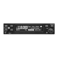
Garmin GTR 200 Installation Manual (84 pages)
COM Transceiver
Brand:
Garmin
| Category:
Transceiver
| Size: 6.6 MB
Table of Contents
Table of Contents
5
Paragraph Page
6
Section 1 General Description
10
Table
10
Section 1 General Description
10
Introduction
10
Equipment Description
10
Table 1-1 Available Units
10
Technical Specifications
11
Table 1-2 Physical Characteristics
11
Table 1-3 General Specifications
11
Table 1-4 Display Specifications
12
Table 1-5 COM Transmitter Specifications
12
Table 1-6 COM Receiver Specifications
13
Certification
14
Reference Documents
14
Table 1-7 FCC Grant of Equipment Authorization
14
Table 1-8 Reference Documents
14
Section 2 Installation Overview
15
Section 2 Installation Overview
15
Introduction
15
Unit Configurations
15
Available Accessories
15
Table 2-1 Catalog Part Numbers
15
Table 2-2 Standard Kit Accessories
15
Installation Considerations
16
Antenna Considerations
16
Table 2-4 Optional Accessories
16
Mounting Considerations
18
Cabling and Wiring
18
Section 2 Installation Overview
19
Figure 2-1 CAN Bus Configuration
19
Air Circulation and Cooling
20
Compass Safe Distance
20
Section 3 Installation Procedures
21
Section 3 Installation Procedures
21
Unpacking the Unit
21
Wiring Harness Installation
21
Table 3-1 Recommended Crimp Tools (or Equivalent)
21
Table 3-2 Socket Contact Part Numbers
21
Backshell Assembly
22
Mounting Requirements
22
Antenna Installation and Connections
23
Section 3 Installation Procedures
24
Post Installation Configuration and Checkout Procedures
24
Figure 3-1 GTR 200 Front Panel
24
Figure 3-2 Configuration Mode Home Page
25
Table 3-3 Configuration Default Settings
26
Figure 3-3 COM Setup Page
27
Figure 3-4 ICS Sidetone Selection
27
Table 3-4 COM Setup Page Selections
27
Figure 3-5 MON Swap Selection
28
Figure 3-6 Audio Setup Page (AUX and Music Disabled)
29
Figure 3-7 Audio Setup Page (AUX and Music Enabled)
29
Table 3-5 Audio Setup Page Selections
29
Figure 3-8 Softkey Setup Page
30
Table 3-6 Softkey Setup Page Selections
30
Figure 3-9 Discrete Setup Page
31
Table 3-7 Discrete Setup Page Selections
31
Figure 3-10 Lighting Setup Page
32
Table 3-8 Lighting Setup Page Selections
32
Figure 3-11 Lighting Graph
33
Figure 3-12 RS-232 Status Page
33
Figure 3-13 Headset Tests Page
34
Figure 3-14 COM Tests Page
35
Figure 3-15 Audio Tests Page
36
Table 3-9 Audio Tests Source Selections
36
Table 3-10 Discrete Inputs
37
Table 3-11 TX Interlock Connections
38
Unit Software
40
Figure 3-16 about Page
40
Figure 3-17 Software Update Page
40
Figure 3-18 Micro SD Insertion
41
Figure 3-19 Software Update Page - Scanning Card
41
Continued Airworthiness
42
Figure 3-20 Software Update Page - no Update Found
42
Figure 3-21 Software Update Page - Update Software
42
Figure 3-22 Software Update Page - Preparing Update
42
Figure 3-23 Software Update Page - Unit will Reboot
42
Section 4 Connector Pinout Information
43
Section 4 Connector Pinout Information
43
Section 4 Connector Pinout Information
43
Pin Function List
43
Figure 4-1 J2001 Looking at Rear of Unit
43
Table 4-1 J2001 Connector
43
Power
44
Lighting Bus
44
CAN Bus
45
Unit ID
45
Figure 4-2 CAN Bus Termination for GTR 200
45
Serial Data - RS-232
46
MIC Audio
46
Aux Mono Audio
47
Headset Audio
47
Music Inputs
47
Paragraph
48
Receiver Audio
48
Pilot/Copilot PTT Inputs
48
TX Interlock
48
Discrete Inputs
49
Appendix A Shield Block Connector Installation Instructions
50
Appendix A Shield Block Connector Installation Instructions
50
Shield Block Installation Parts
50
Table A-1 Parts Not Supplied for a Shield Block Installation (Figure
50
Appendix A Shield Block Connector Installation Instructions
51
Figure A-1 Shield Block Install Onto a Backshell
51
Figure A-2 Method A.1 for Shield Termination
52
Shield Termination Technique - Method A.1 (Standard
52
Table A-2 Shielded Cable Preparations for Garmin Connectors
52
Figure A-3 Insulation/Contact Clearance
54
Figure A-4 Method A.2 (Daisy Chain) for Shield Termination
56
Shield Termination - Method B.1 (Quick Term
56
Shield Termination Technique - Method A.2 (Daisy Chain
56
Figure
57
Figure A-5 Method B.1 (Quick Term) for Shield Termination
57
Figure A-6 Method B.2 (Daisy Chain-Quick Term) for Shield Termination
58
Shield Termination-Method B.2 (Daisy Chain-Quick Term
58
Table A-3 Shielded Cable Preparations - (Quick Term
58
Daisy Chain between Methods a and B
59
Figure A-7 Daisy Chain between Methods a and B
59
Splicing Signal Wires
59
Figure A-8 D-Sub Spliced Signal Wire Illustration
60
Appendix B Serial Interface Specifications
61
Electrical Interface
61
Message Formats
61
Appendix C Outline and Installation Drawings
73
Figure C-1 GTR 200 Outline Drawing
73
Appendix C Outline and Installation Drawings
73
Appendix C Outline and Installation Drawings
74
Figure C-2 GTR 200 Assembly Drawing
74
Figure C-3 GTR 200 Installation Drawing
75
Figure C-4 GTR 200 Panel Cutout Drawing
76
Appendix D Interconnect Examples
77
Appendix D Interconnect Examples
77
Figure D-1 GTR 200 Interconnect Example Notes
77
Figure D-2 GTR 200- Power & Ground/Intercom/Gdu 37X/46X CAN Bus Interconnect Example
78
190-01553-00 GTR 200 Installation Manual
79
Figure D-3 GTR 200- Power & Ground/Intercom/Gdu 37X RS-232 Interconnect Example
79
Figure D-4 GTR 200- Power & Ground/Gma 240/GNS 430/Aera 79X Interconnect Example
80
Figure D-5 GTR 200- Mono Audio/Remote Mount Jack Interconnect Example
81
Figure D-6 GTR 200/CAN Bus Interconnect Drawing
82
Figure D-7 Dual GTR 200/GMA 240 Interconnect Drawing
83
Figure D-8 GTR 200- J2001 Connector Layout
84
Garmin GTR 200 Installation Manual (85 pages)
COM Transceiver
Brand:
Garmin
| Category:
Transceiver
| Size: 6.16 MB
Table of Contents
Table of Contents
7
Paragraph Page
8
Section 1 General Description
13
Table
13
Section 1 General Description
13
Introduction
13
Equipment Description
13
Table 1-1 Available Units
13
Technical Specifications
14
Table 1-2 Physical Characteristics
14
Table 1-3 General Specifications
14
Table 1-4 Display Specifications
15
Table 1-5 COM Transmitter Specifications
15
Table 1-6 COM Receiver Specifications
16
Certification
17
Reference Documents
17
Table 1-7 FCC Grant of Equipment Authorization
17
Table 1-8 Reference Documents
17
Section 2 Installation Overview
19
Section 2 Installation Overview
19
Introduction
19
Unit Configurations
19
Available Accessories
19
Table 2-1 Catalog Part Numbers
19
Table 2-2 Standard Kit Accessories
19
Installation Considerations
20
Antenna Considerations
20
Table 2-4 Optional Accessories
20
Mounting Considerations
22
Cabling and Wiring
22
Air Circulation and Cooling
23
Compass Safe Distance
23
Section 2 2-1 –
24
Section 3 Installation Procedures
25
Section 3 Installation Procedures
25
Unpacking the Unit
25
Wiring Harness Installation
25
Table 3-1 Recommended Crimp Tools (or Equivalent)
25
Table 3-2 Socket Contact Part Numbers
25
Backshell Assembly
26
Mounting Requirements
26
Antenna Installation and Connections
27
Section 3 Installation Procedures
28
Post Installation Configuration and Checkout Procedures
28
Figure 3-1 GTR 200 Front Panel
28
Figure 3-2 Configuration Mode Home Page
29
Table 3-3 Configuration Default Settings
30
Figure 3-3 COM Setup Page
31
Table 3-4 COM Setup Page Selections
31
Figure 3-4 ICS Sidetone Selection
32
Figure 3-5 Audio Setup Page (AUX and Music Disabled)
33
Figure 3-6 Audio Setup Page (AUX and Music Enabled)
33
Table 3-5 Audio Setup Page Selections
33
Figure 3-7 Softkey Setup Page
34
Table 3-6 Softkey Setup Page Selections
34
Figure 3-8 Discrete Setup Page
35
Table 3-7 Discrete Setup Page Selections
35
Figure 3-9 Lighting Setup Page
36
Table 3-8 Lighting Setup Page Selections
36
Figure 3-10 Lighting Graph
37
Figure 3-11 RS-232 Status Page
37
Figure 3-12 Headset Tests Page
38
Figure 3-13 COM Tests Page
39
Figure 3-14 Audio Tests Page
40
Table 3-9 Audio Tests Source Selections
40
Table 3-10 Discrete Inputs
41
Table 3-11 TX Interlock Connections
42
Unit Software
44
Figure 3-15 about Page
44
Figure 3-16 Software Update Page
44
Figure 3-17 Micro SD Insertion
45
Figure 3-18 Software Update Page - Scanning Card
45
Section 3 3-1 –
46
Continued Airworthiness
46
Figure 3-19 Software Update Page - no Update Found
46
Figure 3-20 Software Update Page - Update Software
46
Figure 3-21 Software Update Page - Preparing Update
46
Figure 3-22 Software Update Page - Unit will Reboot
46
Section 4 Connector Pinout Information
47
Section 4 Connector Pinout Information
47
Section 4 Connector Pinout Information
47
Pin Function List
47
Figure 4-1 J2001 Looking at Rear of Unit
47
Table 4-1 J2001 Connector
47
Power
48
Lighting Bus
48
Serial Data - RS-232
49
Aux Mono Audio
49
Headset Audio
50
Music Inputs
50
Receiver Audio
50
Pilot/Copilot PTT Inputs
51
TX Interlock
51
Discrete Inputs
51
Section 4 4-1 –
52
Appendix A Shield Block Connector Installation Instructions
53
Paragraph
53
Appendix A Shield Block Connector Installation Instructions
53
Shield Block Installation Parts
53
Table A-1 Parts Not Supplied for a Shield Block Installation (Figure
53
Appendix A Shield Block Connector Installation Instructions
54
Figure A-1 Shield Block Install Onto a Backshell
54
Figure A-2 Method A.1 for Shield Termination
55
Shield Termination Technique - Method A.1 (Standard
55
Table A-2 Shielded Cable Preparations for Garmin Connectors
55
Figure A-3 Insulation/Contact Clearance
57
Figure A-4 Method A.2 (Daisy Chain) for Shield Termination
59
Shield Termination - Method B.1 (Quick Term
59
Shield Termination Technique - Method A.2 (Daisy Chain
59
Figure A-5 Method B.1 (Quick Term) for Shield Termination
60
Figure A-6 Method B.2 (Daisy Chain-Quick Term) for Shield Termination
61
Shield Termination-Method B.2 (Daisy Chain-Quick Term
61
Table A-3 Shielded Cable Preparations - (Quick Term
61
Daisy Chain between Methods a and B
62
Figure A-7 Daisy Chain between Methods a and B
62
Splicing Signal Wires
62
Figure
63
Figure A-8 D-Sub Spliced Signal Wire Illustration
63
Appendix B Serial Interface Specifications
65
Electrical Interface
65
Message Formats
65
Appendix C Outline and Installation Drawings
77
Appendix C Outline and Installation Drawings
77
Figure C-1 GTR 200 Outline Drawing
77
Appendix C Outline and Installation Drawings
78
Figure C-2 GTR 200 Assembly Drawing
78
Figure C-3 GTR 200 Installation Drawing
79
Figure C-4 GTR 200 Panel Cutout Drawing
80
Appendix D Interconnect Examples
81
Appendix D Interconnect Examples
81
Figure D-1 GTR 200 Interconnect Example Notes
81
Figure D-2 GTR 200- Power & Ground/Intercom/Gdu 37X Interconnect Example
82
Figure D-3 GTR 200- Power & Ground/Gma 240/GNS 430/Aera 79X Interconnect Example
83
Figure D-4 GTR 200- Mono Audio/Remote Mount Jack Interconnect Example
84
Figure D-5 GTR 200- J2001 Connector Layout
85
Advertisement
Garmin GTR 200 Pilot's Manual (34 pages)
Brand:
Garmin
| Category:
Transceiver
| Size: 0.55 MB
Table of Contents
Table of Contents
9
Description
11
Display
11
Controls
12
Softkeys
13
Basic Operation
14
Power-UP
14
COM Radio
14
Selecting a COM Frequency
14
Adjusting Volume
15
Standby COM Frequency Monitoring
15
Monitoring the Standby COM Frequency
15
COM Frequency Storage
15
Saving a COM Frequency
15
Editing a Saved COM Frequency
17
Accessing the COM Frequency Groups
18
Emergency Channel
19
Quick Tuning the Emergency Channel
19
Stuck MIC
19
Main Menu
20
Accessing/Using the Main Menu
20
Media Page (GTR 200B Only)
21
Accessing/Using the MEDIA Page
21
Telephone Page (GTR 200B Only)
22
Accessing/Using the TELEPHONE Page
22
Bluetooth ® Page (GTR 200B Only)
23
Bluetooth Pairing
23
Setup Menu
24
Accessing/Using the SETUP Menu
25
3D Audio
25
Enabling/Disabling 3D Audio
26
About Screen
27
Accessing the about Menu
27
Ics Configuration
28
Setting the ICS Volume
28
Setting the ICS Squelch
28
Enable/Disable Pilot Isolation
28
Gtr 200/200B
29
Appendix
29
Softkey Configuration
29
Configuring Softkeys
29
Troubleshooting
30
Messages
31
Garmin GTR 200 Pilot's Manual (30 pages)
GTR 200 Pilot's Guide
Brand:
Garmin
| Category:
GPS
| Size: 0.52 MB
Table of Contents
Product Registration and Support
7
Table of Contents
9
Description
11
Display
11
Controls
12
Softkeys
13
Basic Operation
14
Power-UP
14
COM Radio
14
Selecting a COM Frequency
14
Adjusting Volume
14
Standby COM Frequency Monitoring
15
Monitoring the Standby COM Frequency
15
COM Frequency Storage
15
Saving a COM Frequency
15
Editing a Saved COM Frequency
16
Accessing the COM Frequency Groups
17
Emergency Channel
18
Quick Tuning the Emergency Channel
18
Stuck MIC
18
Main Menu
19
Accessing/Using the Main Menu
19
Setup Menu
19
Accessing/Using the SETUP Menu
20
3D Audio
20
Enabling/Disabling 3D Audio
21
About Screen
22
Accessing the about Menu
22
Ics Configuration
23
Setting the ICS Volume
23
Setting the ICS Squelch
23
Enable/Disable Pilot Isolation
23
Appendix
24
Softkey Configuration
24
Configuring Softkeys
24
Troubleshooting
25
Messages
25
Advertisement
Related Products
Garmin GTR 225
Garmin GTR 205
Garmin GTU 10
Garmin GTP 59
Garmin GTN 7 series
Garmin GTM 60
Garmin GTN 625
Garmin GTN 650
Garmin GTS 820
Garmin GTS 8000
Garmin Categories
GPS
Watch
Car Navigation system
Avionics Display
Marine GPS System
More Garmin Manuals
Login
Sign In
OR
Sign in with Facebook
Sign in with Google
Upload manual
Upload from disk
Upload from URL