Sign In
Upload
Manuals
Brands
Garmin Manuals
Avionics Display
GA 55
Garmin GA 55 Manuals
Manuals and User Guides for Garmin GA 55. We have
2
Garmin GA 55 manuals available for free PDF download: Pilot's Manual, Installation Manual
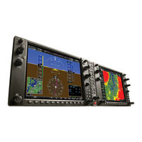
Garmin GA 55 Pilot's Manual (482 pages)
Integrated Flight Deck for the Piper PA-32 Saratoga Series
Brand:
Garmin
| Category:
Avionics Display
| Size: 34 MB
Table of Contents
Table of Contents
17
Section 1 System Overview
21
System Description
21
Line Replaceable Units
22
Secure Digital (SD) Cards
24
Applying Power to the System
25
System Operation
26
Normal Display Operation
26
Reversionary Display Operation
26
System Annunciations
27
AHRS Operation
29
GPS Receiver Operation
31
System Controls
36
PFD/MFD Controls
36
Softkey Function
38
Accessing System Functionality
43
Menus
43
Data Entry
43
Page Groups
44
System Setup and Status Pages
46
System Utilities
55
Display Backlighting
61
Section 2 Flight Instruments
63
Flight Instruments
66
Airspeed Indicator
66
Attitude Indicator
68
Altimeter
69
Vertical Speed Indicator (VSI)
72
Vertical Deviation
72
Horizontal Situation Indicator (HSI)
73
Course Deviation Indicator (CDI)
78
Supplemental Flight Data
85
Temperature Displays
85
Wind Data
85
Vertical Navigation (VNV) Indications
86
Garmin Synthetic Vision Technology (SVT) (Optional)
88
SVT Operation
89
SVT Features
90
Field of View
99
PFD Annunciations and Alerting Functions
101
Marker Beacon Annunciations
101
Altitude Alerting
101
Low Altitude Annunciation
102
Minimum Altitude Alerting
102
Abnormal Operations
104
Abnormal GPS Conditions
104
Unusual Attitudes
105
Section 3 Engine Indication System
109
Engine Display
110
Engine Page
112
Engine Softkeys
112
Fuel Calculations
114
EIS Display (Reversionary Mode)
115
Engine Softkeys (Reversionary Mode)
116
Lean Display
117
System Display
120
Section 4 Audio Panel and Cns
123
Overview
123
MFD/PFD Controls and Frequency Display
124
Audio Panel Controls
126
COM Operation
128
COM Tuning Boxes
128
COM Transceiver Manual Tuning
129
Quick-Tuning and Activating 121.500 Mhz
130
Auto-Tuning the COM Frequency
130
Frequency Spacing
134
Automatic Squelch
135
Volume
136
NAV Operation
137
NAV Radio Selection and Activation
137
NAV Receiver Manual Tuning
137
Auto-Tuning a NAV Frequency from the MFD
139
Marker Beacon Receiver
143
ADF/DME Tuning
144
Mode S Transponder
148
Transponder Controls
148
Transponder Mode Selection
149
Entering a Transponder Code
151
IDENT Function
152
Additional Audio Panel Functions
153
Power Application
153
Mono/Stereo Headsets
153
Speaker
153
Intercom
153
Passenger Address (PA) System
155
Clearance Recorder and Player
155
Split COM
156
Entertainment Inputs
157
Audio Panel Preflight Procedure
158
Abnormal Operation
159
Stuck Microphone
159
COM Tuning Failure
159
Audio Panel Fail-Safe Operation
159
Reversionary Mode
159
Section 5 Flight Management
161
Introduction
161
Navigation Status Box and Data Bar
162
Using Map Displays
164
Map Orientation
164
Map Range
166
Map Panning
168
Measuring Bearing and Distance
171
Topography
172
Map Symbols
174
Additional Navigation Map Items
182
Waypoints
188
Airports
189
Intersections
196
Ndbs
197
Vors
199
VRP S
201
User Waypoints
202
Airspaces
209
Direct-To Navigation
213
Flight Planning
218
Selection and Modification Methods
219
Flight Plan Display
221
Creating a Flight Plan
223
Flight Plan Waypoint and Airway Modifications
224
Flight Plan Operations
231
Managing Flight Plans
240
Vertical Navigation
248
Altitude Constraints
250
Procedures
253
Departures
254
Arrivals
256
Approaches
258
Weight and Fuel
269
Weight and Fuel Planning
269
Weight Caution and Warning Conditions
271
Trip Planning
272
Abnormal Operation
276
Dead Reckoning
276
Section 6 Hazard Avoidance
279
Siriusxm Weather
280
Activating Services
280
Using Siriusxm Weather Products
281
FIS-B Weather
312
Using FIS-B Weather Products
312
FIS-B Weather Status
324
Stormscope Lightning
325
Setting up Stormscope on the Navigation Map
326
Selecting the Stormscope Page
329
Terrain Proximity
331
Displaying Terrain Proximity Data
332
Terrain Proximity Page
334
Terrain-SVS
336
Displaying Terrain-SVS Data
337
MAP - Terrain-SVS Page
339
System Status
343
Taws-B
345
Displaying TAWS-B Data
346
TAWS-B Page
349
TAWS-B Alerts
350
System Status
357
Profile View Terrain
359
Profile View Display
359
Profile Path
361
Traffic Information Service (TIS)
362
Displaying TRAFFIC Data
363
MAP - Traffic Map Page
364
TIS Alerts
365
System Status
367
Skywatch SKY497 Traffic Advisory System
370
TAS Symbology
370
Traffic Alerts
372
System Test
373
Operation
374
Garmin ADS-B Traffic
382
ADS-B System Overview
382
ADS-B with TAS
383
Conflict Situational Awareness & Alerting
383
Airborne and Surface Applications
386
Traffic Description
387
Operation
387
System Status
396
Section 7 Automatic Flight Control System
399
S-TEC Fifty Five X Autopilot (Optional)
399
Flight Director Mode Annunciation
399
Altitude Preselect
399
Section 8 Additional Features
401
Safetaxi
402
Chartview
405
Chartview Softkeys
406
Terminal Procedures Charts
406
Day/Night View
412
Flitecharts
415
Flitecharts Softkeys
416
Terminal Procedures Charts
417
Chart Options
421
Day/Night View
421
Siriusxm Satellite Radio Entertainment
422
Activating Siriusxm Satellite Radio Services
422
Using Siriusxm Satellite Radio
423
Flight Data Logging
427
Electronic Checklists
429
Abnormal Operation
432
Siriusxm Data Link Receiver Troubleshooting
432
Annunciations and Alerts
435
CAS Message Prioritization
436
CAS Annunciations
437
Message Advisory Alerts
438
System Message Advisories
439
Database Management
449
Navigation Databases
450
Dual Navigation Database Feature
452
Garmin Databases
454
Frequently Asked Questions
471
Index
475
Advertisement
Garmin GA 55 Installation Manual (90 pages)
Brand:
Garmin
| Category:
GPS
| Size: 6 MB
Table of Contents
Installation Manual
1
Table of Contents
4
Paragraph Page
5
Limited Warranty
10
Section 1 GDU 37X Installation Overview
11
Unpacking Unit
11
Introduction
11
System Overview
11
Section 1 GDU 37X Installation Overview
12
General GDU 37X LRU Specifications
12
Garmin LRU Part Numbers
12
Power Specifications
12
Physical Specifications
12
GDU 37X LRU Part Numbers
12
Contents of GDU 37X Assembly (010-00667-XX)
12
GDU 37X LRU Power Requirements
12
GDU 37X LRU Physical Specifications
12
Cooling Requirements
13
Mounting
13
Wiring/Cabling Considerations
13
Wiring Harness Installation
13
Cable Location Considerations
14
Pin Contact and Crimp Tools Part Numbers
14
Cable Installation
15
Backshell Assemblies
15
Coax Cable Installation
15
Section 2 GDU 37X
17
Equipment Description
17
Navigation Functions
17
Interface Summary
17
Section 2 GDU 37X
18
Electrical Specifications
18
Electrical Characteristics
18
Power Consumption
18
GPS Specifications
18
GDU 37X Supply Voltages
18
GDU 37X Power Requirements
18
GDU 37X GPS Specifications
18
Antennas
19
Environmental Specifications
19
Installation Requirements
20
Required Accessories
20
Additional Equipment Required
20
Section 2 GDU 37X
20
GDU 37X Mounting Accessories
20
Contents of GDU 37X Connector Kit (011-01921-00)*
20
GDU 37X Required Accessories
20
Continued Airworthiness
21
Installation Considerations
21
Mounting Requirements
21
Unit Installation
21
GDU 37X Panel Cutout Template
22
Panel Cutout Template
22
Section 2 2-1 –
22
Section 3 Garmin GPS/XM Antennas
23
Section 3 Garmin GPS/XM Antennas
23
GPS Antennas
23
XM Antennas
23
GPS Antenna Minimum Requirements
23
Antenna Mounting Considerations
24
VHF COM/GPS Interference
24
XM Satellite Radio Antenna Minimum Requirements
24
GPS/XM Antenna Mounting Location
25
Section 3 Garmin GPS/XM Antennas
26
Recommended Antenna Placement
26
Buried Antenna (below the Skin Covering or Glareshield) Mounting
27
Carbon/Glass Buried Antenna Area
27
Antenna Doubler/Backing Plate
28
Antenna Grounding Plane
28
Glare Shield Buried Antenna Area
28
Antenna Grounding
29
Teardrop Footprint Antenna Installation (GA 55 and GA 56)
29
Preparation of Doubler
29
Teardrop Footprint Antenna Doubler Design and Installation
29
Antenna Installation Instructions
30
Reference Figures
30
Paragraph
29
Doubler Design, Teardrop Footprint Antenna, Skin Thickness 0.032" to 0.049"
30
Doubler Design, Teardrop Footprint Antenna, Skin Thickness 0.049" to 0.051"
31
Doubler Design, Teardrop Footprint Antenna, Skin Thickness 0.051" to 0.063"
31
Sample Doubler Location, Teardrop Footprint Antenna, Metal Skin Aircraft
32
Skin Cutout Detail, Teardrop Footprint Antenna, Skin Thickness 0.032" to 0.049"
32
ARINC 743 Footprint Antenna Installation (GA 55A, GA 57X)
35
ARINC 743 Footprint Antenna Doubler Design and Installation
35
Preparation of Doubler
36
Antenna Installation Instructions
36
Reference Figures
37
Doubler Design, ARINC 743 Footprint Antenna, Skin Thickness 0.032" to 0.049"
37
Doubler Design, ARINC 743 Footprint Antenna, Skin Thickness 0.049" to 0.051"
38
Doubler Design, ARINC 743 Footprint Antenna, Skin Thickness 0.051" to 0.063"
39
Sample Doubler Location, ARINC 743 Antenna, Metal Skin Aircraft
40
Skin Cutout Detail, ARINC 743 Footprint Antenna, Skin Thickness 0.032" to 0.049"
40
Doubler Installation, ARINC 743 Footprint, Skin Thickness 0.051" to 0.063"
43
Installation of ARINC 743 Footprint Antenna
43
Non-Structural Mount Installation
44
Generic Non-Structural Antenna Installation
44
Generic Non-Structural ARINC 743 Footprint Antenna Installation
44
Considerations for Non-Structural Mounting
45
Non-Structural Installation to Glareshield
45
Example Bracket Antenna Mounting under Glareshield
45
Example Non-Structural Antenna Mounting under Glareshield
46
Non-Structural Installation to Airframe
47
Example Teardrop Antenna Installation in Airframe under Fabric Skin
47
Example ARINC 743 Footprint in Airframe under Fabric Skin
47
Example Non-Structural Antenna Mounting on Airframe
48
Example Teardrop Footprint Antenna Mounting under Fabric Skin
49
Minimum Distance Required between Tube Structure and Antenna
49
Section 3 3-1 –
50
Section 4 Software, Configuration, Databases, and XM Activation
51
Configuration Mode
51
Software/Audio Data Identification
51
LRU Software and Audio Data Version Identification
51
Software Loading Procedure
52
GDU Software Loading Procedure
52
Configuration
53
Main Configuration Page
53
ACFT Configuration Page
54
W/B (Weight/Balance) Configuration Page
55
UNITS Configuration Page
56
DSPL (Display) Configuration Page
57
SOUND Configuration Page
59
COMM Configuration Page
60
Garmin Database Updates
61
Updating Garmin Databases
61
Available Databases
63
Section 4 4-1 –
64
XM Activation Instructions (GDU 375 Only)
64
Section 5 Post-Installation Checkout Procedure
65
Required Test Equipment
65
GDU 37X Test Procedure
65
Section 5 5-1 –
66
Appendix A GDU 37X Pinouts
67
Appendix A GDU 37X Pinouts
67
Gdu 37X
67
P3701 Connector
67
View of J3701 Connector from Back of Unit
67
Aircraft Power
68
Demo Mode Selection
68
Serial Data
69
Lighting
69
Audio
69
Appendix B Connector Installation Instructions
71
Paragraph
71
Appendix B Connector Installation Instructions
71
Jackscrew Backshell Installation Instructions
71
Shield Block Installation Parts
71
Parts Supplied for a Shield Block Installation (Figure B-1)
71
Parts Not Supplied for a Shield Block Installation (Figure B-1)
71
Appendix B Connector Installation Instructions
72
Shield Install Onto a Jackscrew Backshell (78 Pin Example)
72
Shield Termination Technique - Method A.1 (Standard
73
Method A.1 for Shield Termination
73
Shielded Cable Preparations for Garmin Connectors
73
Insulation/Contact Clearance
75
Shield Termination Technique - Method A.2 (Daisy Chain
77
Method A.2 (Daisy Chain) for Shield Termination
77
Shield Termination - Method B.1 (Quick Term
78
Method B.1 (Quick Term) for Shield Termination
79
Shielded Cable Preparations – (Quick Term)
79
Method B.2 (Daisy Chain-Quick Term) for Shield Termination
80
Shield Termination-Method B.2 (Daisy Chain-Quick Term
80
Daisy Chain between Methods a and B
81
Double-Shield Termination Technique - Method
82
Method C.1 Double-Shield Termination
82
Shielded Cable Preparations for Garmin Connectors
82
Double-Shield Termination Technique (Quick Term) - Method
83
ID Program Pins (Strapping
83
Method C.2 Double-Shield Termination
83
Splicing Signal Wires
84
D-Sub Spliced Signal Wire Illustration
84
Appendix C Outline and Installation Drawings
85
GDU 37X Outline Drawing
85
GDU Panel Cutout Drawing
86
GA 55/55A Installation Drawing
87
GA 56 Installation Drawing
88
GA 57X Installation Drawing
89
Appendix D Interconnect Drawing (Example Only)
90
GDU 37X Interconnect Drawing
90
Advertisement
Related Products
Garmin GAP 26
Garmin G600
Garmin G1000:Piper
Garmin G1000:Socata
Garmin GMA 350
Garmin GNC 420
Garmin GPS 400, GNC 420
Garmin GDL 49
Garmin GMA 245R
Garmin GSU 75 Series
Garmin Categories
GPS
Watch
Car Navigation system
Avionics Display
Marine Equipment
More Garmin Manuals
Login
Sign In
OR
Sign in with Facebook
Sign in with Google
Upload manual
Upload from disk
Upload from URL