Table of Contents
Advertisement
Quick Links
POWER
1
0
K
V
A
D
1
0
K
V
A
D
T
R
U
T
R
U
input and output voltage options:
14 Hartom St., PO Box 45029, Jerusalem 97774, Israel
Tel: +972-2-588-8222
Email: info@gamatronic.co.il
C
C
O
U
B
L
E
O
O
U
B
L
E
O
-
-
E
O
N
L
I
N
E
E
O
N
L
I
N
E
User-configurable
I
I
N
N
P
P
U
U
T
T
3
4
0
0
V
3
4
0
0
V
X
X
3
3
4
4
0
0
0
0
V
V
X
X
1
2
3
0
V
1
2
3
0
V
X
X
User Guide
Release 1.6, December 2006
Har Hotzvim Industrial Park,
Fax: +972-2-582-8875
Web: www.gamatronic.com
+
SA
N
V
E
R
S
I
O
N
N
V
E
R
S
I
O
N
B
A
T
T
E
R
Y
B
A
T
T
E
R
Y
O
O
U
U
T
T
P
U
T
T
P
U
3
4
0
0
V
3
4
0
0
V
X
X
1
1
2
2
3
3
0
0
V
V
X
X
1
2
3
0
V
1
2
3
0
V
X
X
U
P
S
U
P
S
2MUM-PPSA/2
Advertisement
Table of Contents

Subscribe to Our Youtube Channel
Related Manuals for Gamatronic POWER+ SA


Summary of Contents for Gamatronic POWER+ SA
- Page 1 POWER User-configurable input and output voltage options: User Guide Release 1.6, December 2006 Har Hotzvim Industrial Park, 14 Hartom St., PO Box 45029, Jerusalem 97774, Israel Tel: +972-2-588-8222 Fax: +972-2-582-8875 Email: info@gamatronic.co.il Web: www.gamatronic.com 2MUM-PPSA/2...
- Page 2 Neither this document nor the information contained herein may be published, or reproduced, in whole or in part, without the express, prior, written permission of Gamatronic Electronic Industries Ltd. In addition, any use of this document or the information contained herein for any purposes other than those for which it was disclosed is strictly forbidden.
-
Page 3: Table Of Contents
TO ITS BASE ......................AFETY ONSIDERATIONS Do’s ..........................vii Don’ts ..........................vii ........................1 NTRODUCTION Major Parts of the POWER+ SA ..................2 Control Panel........................2 Charger..........................2 Inverter ..........................3 Static Switch (ST/SW) ...................... 3 Battery ..........................3 ......................4 PERATING ODES Normal Mode ........................ - Page 4 Gamatronic Electronic Industries Ltd. Set Automatic Restart mode (optional) ................44 Operation........................44 ..................45 ETTING YSTEM ARAMETERS Setting the system clock ....................45 Setting screen contrast ....................46 Changing the nominal output voltage................47 Fine-tune the output voltage ..................48 .......................
-
Page 5: Conventions Used In This Book
Gamatronic Electronic Industries Ltd. ONVENTIONS USED IN THIS BOOK The POWER + SA UPS is capable of operating with any of three possible line configurations: • 3-phase input – 3-phase output (abbreviated “3-3” ) • 3-phase input – 1-phase output (abbreviated “3-1”) •... -
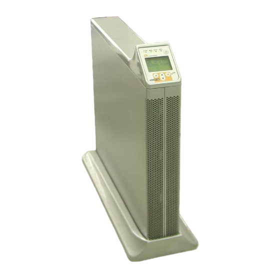
Page 6: Attaching The Power + Sa
Gamatronic Electronic Industries Ltd. POWER + SA TTACHING THE TO ITS BASE POWER + Attaching the Stand-Alone to its base POWER + SA User Guide, Release 1.6... -
Page 7: Safety Considerations
Gamatronic Electronic Industries Ltd. AFETY ONSIDERATIONS The POWER + SA UPS system is designed for industrial applications and harsh environments. Nevertheless the POWER + SA UPS system is a sophisticated power system and should be handled with appropriate care, following these guidelines. - Page 8 Gamatronic Electronic Industries Ltd. WARNING: RISK OF SEVERE DAMAGE TO THE UPS!!! NEUTRAL HIS SYSTEM USES THE LINE FOR OPERATION HEREFORE IT IS STRICTLY FORBIDDEN TO CONNECT THIS SYSTEM TO POWER SOURCE WITHOUT A NEUTRAL NULL CONDUCTOR AILURE TO USE A NEUTRAL CONDUCTOR MAY CAUSE PERMANENT DAMAGE TO THE SYSTEM POWER + SA User Guide, Release 1.6...
-
Page 9: Introduction
The efficiency of POWER + SA thus helps to extend the life of your equipment, even during normal use when the input power is constant and continuous. POWER+ SA is unique because it • Is a true on-line battery design according to IEC 62040-3 •... -
Page 10: Major Parts Of The Power+ Sa
Gamatronic Electronic Industries Ltd. Major Parts of the POWER+ SA The POWER + SA includes the following sub-assemblies: The POWER+ SA CONTROL PANEL The POWER + SA control panel allows the user to: manage and control the POWER + SA •... -
Page 11: Inverter
The batteries are housed in an external cabinet next to the POWER + SA cabinet. Batteries are charged by the rectifier, which supplies both the inverter and the battery charger. Basic schematic of the POWER+ SA POWER + SA User Guide, Release 1.6... -
Page 12: Operating Modes
Bypass mode Normal Mode POWER+ SA almost always operates in normal mode. In normal mode the load receives its power from the inverters that supply stabilized voltage, protected from spikes and irregularities in the AC input. The AC input system feeds the charger which supplies DC power to the inverter, while concurrently charging the batteries. -
Page 13: Battery Mode
Gamatronic Electronic Industries Ltd. Battery Mode If the input AC power fails or the voltage drops below an acceptable level, the UPS operates in backup mode. In backup mode the load continues to receive power from the inverters, but the DC input to the inverter is taken from the batteries, instead of from the rectifier. -
Page 15: User Interface
Lets you display other current readings • Lets you modify UPS settings and operating mode The control panel is for use by the end-user and the service technician. The POWER+ SA control panel POWER + SA User Guide, Release 1.6... -
Page 16: On/Off Button
Gamatronic Electronic Industries Ltd. On/Off Button To turn the UPS on, press the button twice. To turn the UPS off, press the button twice. Navigation Keypad The control panel’s keypad consists of three buttons. • The UP/DOWN key is used to navigate through screens and browse the Event Log. -
Page 17: The Power+ Display Screen
The Main Screen The POWER+ SA Main Screen is the default display on the POWER+ SA screen. From any other screen, if the keyboard is not used for 45 seconds, the POWER+ SA returns to the Main Screen. The Main Screen shows the UPS’s current operating mode and other critical data. - Page 18 Gamatronic Electronic Industries Ltd. POWER + SA User Guide, Release 1.6...
-
Page 19: Normal Mode
Gamatronic Electronic Industries Ltd. NORMAL MODE In Normal mode, the Main Screen displays the message: UPS ON, NORMAL MODE. The AC INPUT and NORMAL LEDs are lit. The following picture shows the Main Screen as you will see it most of the time, in Normal Mode. - Page 20 Gamatronic Electronic Industries Ltd. In the event of an overload condition, an icon indicating this appears in the lower right quadrant of the Main Screen, the alarm LED ligits, and the audible alarm sounds. POWER + SA User Guide, Release 1.6...
-
Page 21: Battery Mode
Gamatronic Electronic Industries Ltd. BATTERY MODE When the UPS is operating in battery mode, the Main Screen first displays the message: UPS ON, BATTERY MODE. LED lit LED lit As the battery discharges, the number of “stripes” on the battery icon decreases. - Page 22 Gamatronic Electronic Industries Ltd. When the “BATTERY LOW” message appears, there are only a few seconds before the battery is exhausted. To avoid losing information, you should at this time save your data and perform an orderly shutdown of any computers connected to the UPS, if you have not already done so.
- Page 23 Gamatronic Electronic Industries Ltd. • When auto-restart is ENABLED, the UPS screen is blank; no LEDs are lit. When AC power is restored, the UPS starts up automatically. POWER + SA User Guide, Release 1.6...
-
Page 24: Bypass Mode
Gamatronic Electronic Industries Ltd. BYPASS MODE In Bypass mode, the Main Screen displays the message: ∗ UPS ON, BYPASS MODE. The AC INPUT , BYPASS, and ALARM LEDs are lit. After 60 seconds in Bypass Mode the audible alarm sounds. -
Page 25: Ups Off
Gamatronic Electronic Industries Ltd. UPS OFF Off mode is invoked by pressing the On/Off button twice when the UPS is operating. The Off screen displays the message: UPS OFF, NO OUTPUT. Off mode can also be invoked automatically in the event of an extended AC power outage, if auto-restart is disabled. - Page 26 Gamatronic Electronic Industries Ltd. Off mode can also be invoked remotely, through the RS232 data connection. POWER + SA User Guide, Release 1.6...
-
Page 27: Status Screens
Gamatronic Electronic Industries Ltd. Status Screens From the Main Screen, by means of the button, you can access several screens that provide current UPS status information: • UPS Profile screen • AC Output screen • AC Input screen • Bypass screen •... -
Page 28: Ac Output Screen
Gamatronic Electronic Industries Ltd. To see the second UPS Profile screen, press again. The second UPS Profile screen shows: • Maximum output power rating of your UPS. • Current contrast setting of the display screen (see page 46 for information on the contrast setting). -
Page 29: Ac Input Screen
Gamatronic Electronic Industries Ltd. AC INPUT SCREEN To see the current status of the AC input to the UPS, from the Main Screen, press three times. The checkmark indicates that the AC voltage of each input phase is within an acceptable range;... -
Page 30: Inverter Screen
Gamatronic Electronic Industries Ltd. INVERTER SCREEN To display the current status of the inverter, from the Main Screen, press five times. If the inverter output is phase-synchronized with the Bypass input, the message SYNC OK is shown; otherwise, SYNC FLT (synch fault) appears. -
Page 31: Battery Screen
Gamatronic Electronic Industries Ltd. BATTERY SCREEN To see the current battery status and voltages, from the Main Screen, press times. The battery status can be: • BATTERY OK, • BATTERY LOW, or • BATTERY FLT (means the battery failed the latest battery test). -
Page 32: The Power + Sa Main Menu
The Main Menu is your point of access to a number of informational and control features. To display the Main Menu, from the Main Screen press Ent. . POWER+ SA Main Menu The Main Menu options are described elsewhere in this book:... -
Page 33: Daily Operation
AILY PERATION POWER + SA Start-up This section explains how to start-up the POWER+ SA after a shutdown. You are beginning the process from the UPS OFF NO OUTPUT screen. Press the ON/OFF button twice. The BYPASS and ALARM LEDs light up for about 40 seconds. -
Page 34: Power + Sa Shutdown
Gamatronic Electronic Industries Ltd. POWER + SA Shutdown This section describes the shutdown procedures for the UPS if you want to shut it down for a period of time during which the load devices will not be operating. Begin the process from the UPS ON, NORMAL MODE screen. -
Page 35: The Event Log
In the event of an alarm (the audible alarm sounds or the red alarm light on the POWER+ SA console lights up), go to the Event Log to determine the nature of the problem. (Pressing the Esc key from the Main Screen silences the audible alarm.) -
Page 36: Event Log Entries
Gamatronic Electronic Industries Ltd. Event log entries To see the latest entry in the Event Log, from the Active Alarm display press Ent. To scroll backwards to previous entries, press the Down button. To scroll forwards again to later entries, press the Up button. - Page 37 Gamatronic Electronic Industries Ltd. OUTSTANDING ALARM MESSAGES ALARM Explanation MESSAGE Meaning: The voltage of one or more of the input AC phases is out of range, or there is no AC input at all. The UPS is now in Battery Mode.
- Page 38 Gamatronic Electronic Industries Ltd. Meaning: The batteries have been exhausted, and the UPS has turned itself off. Additional indications: The UPS has turned itself OFF. END OF BACKUP 8kVA, 208V model: The symbol. appears on the Main Screen. 10kVA, 400V model: The UPS screen is blank.
- Page 39 Gamatronic Electronic Industries Ltd. LOG MESSAGES Log Entry Explanation AC LINE FAULT No input voltage to charger. AC LINE OK Input voltage to charger has been restored BATT. TEST FAIL The last battery test failed. The last battery test was successful (following a failed battery BATT.
-
Page 40: Battery Tests
To end the test immediately, press Ent again. If the POWER+ SA batteries fail a battery test, the battery failure icon appears on the POWER+ SA screen and remains there until a later battery test is passed. POWER + SA User Guide, Release 1.6... -
Page 41: First
Gamatronic Electronic Industries Ltd. IRST ETUP Your POWER + SA UPS is capable of operating with any of three possible line configurations. The configuration used by the UPS depends on the AC input supplied and on the UPS settings. The permitted line configurations are shown in the following table. - Page 42 Gamatronic Electronic Industries Ltd. Bypass AC output input AC input Gnd,N,R,S,T Gnd,N,R,S,T Gnd,N,R,S,T Battery input 6 mm 2.5 mm 2.5 mm 2.5 mm (Use the battery cable supplied by Gamatronic.) Using a screwdriver, remove the cable cover from the rear of the POWER+ SA.
- Page 43 Gamatronic Electronic Industries Ltd. The uncovered rear panel is shown in the next illustration. Unplug the green plastic connectors and wire them as labelled. Be sure the wires are not live before you begin. Use wires of the proper diameter, as given on page 34.
-
Page 44: Cable Connections For 3-1 Usage
Gamatronic Electronic Industries Ltd. Connections at the rear of the UPS Connect the wired connectors to the rear of the UPS. Use the supplied battery cable to connect the battery to the UPS. Recheck the connections before continuing. To conceal and protect the cables and terminals, replace the outside cover on the rear of the UPS. - Page 45 2.5 mm (Use the battery cable supplied by Gamatronic.) Using a screwdriver, remove the cable cover from the rear of the POWER+ SA. The uncovered rear panel for the 3-1 configuration is shown in the next illustrations. POWER + SA User Guide, Release 1.6...
- Page 46 Gamatronic Electronic Industries Ltd. Connect the AC Input, Bypass Input, and Output cables to the terminals on the rear panel of the UPS. Ensure the cables are not live before you begin. For the Bypass input, use the R phase for the “Phase” connection.
- Page 47 Gamatronic Electronic Industries Ltd. Use the supplied battery cable to connect the battery to the UPS. Recheck the connections before continuing. To protect and conceal the cables and terminals, replace the outside cover on the rear of the UPS. POWER + SA User Guide, Release 1.6...
-
Page 48: Cable Connections For 1-1 Usage
10 mm (Use the battery cable supplied by Gamatronic.) Using a screwdriver, remove the cable cover from the rear of the POWER+ SA. The uncovered rear panel is shown in the next illustration. POWER + SA User Guide, Release 1.6... - Page 49 Gamatronic Electronic Industries Ltd. Connect the AC Input, Bypass Input, and Output cables to the terminals on the rear panel of the UPS. Ensure the cables are not live before you begin. Use wires of the proper diameter, as given on page 37.
- Page 50 Gamatronic Electronic Industries Ltd. Use the supplied battery cable to connect the battery to the UPS. Recheck the connections before continuing. To protect and conceal the cables and terminals, replace the outside cover on the rear of the UPS. POWER + SA User Guide, Release 1.6...
-
Page 51: Installation And Start-Up Sequence
Gamatronic Electronic Industries Ltd. Installation and Start-Up Sequence To start the UPS: Attach the load device, if desired, but do not turn it on until you have set the UPS output voltage, as described below. Turn on the circuit breakers for the AC input, the Bypass input, and the Battery. -
Page 52: Set The System Clock
To turn the UPS on, press the ON/OFF button twice and wait a few seconds. The following screen is displayed. The “AC Input” and “Normal” LEDs should be lit. Turn on the AC output circuit breaker. You can now operate the equipment attached to the POWER+ SA. POWER + SA User Guide, Release 1.6... -
Page 53: Setting System Parameters
From the Main Screen, press the Ent button to display the Main Menu. On the Main Menu, select SET CLOCK and press Ent. This displays the CLOCK screen, which shows the current time and date according to the POWER+ SA clock. The information is displayed in the format HH:MM:SS DD:MM:YYYY To change the time and date, press Ent. -
Page 54: Setting Screen Contrast
Gamatronic Electronic Industries Ltd. Setting screen contrast The screen contrast function controls the visibity of the message text against the screen background. The default setting of 144 is usually satisfactory, but you can modify the default setting between the values of 0 and about 210, if needed. -
Page 55: Changing The Nominal Output Voltage
To change the nominal output voltage: If the POWER+ SA is not already in “off” mode, press the ON/OFF button twice to turn the UPS off. From the Main Screen, press the Ent button to display the Main Menu. -
Page 56: Fine-Tune The Output Voltage
Gamatronic Electronic Industries Ltd. The UPS fans may stop working for a moment. They will start up again by themselves after the voltage adjustment is complete. Press Esc to return to the Main screen. Fine-tune the output voltage You have the ability to “fine-tune” the UPS output voltage. You can adjust each phase of the output voltage up and down by one or more volts, if needed. - Page 57 Gamatronic Electronic Industries Ltd. You are asked to choose the output phase to be adjusted. Select the desired phase and press Ent. Indicate the adjustment to be made to the output voltage of the selected phase. For example, if the output voltage is currently 210 volts and you want to change it to 212, press the UP button twice to cause “2”...
-
Page 58: Automatic Restart
In the event of a prolonged power outage, the UPS turns itself off automatically after the batteries have been exhausted. You can instruct the POWER+ SA to start up automatically so that it will supply current to the load devices when the AC power is restored. - Page 59 Gamatronic Electronic Industries Ltd. Press Ent to change the automatic restart status. The new automatic restart status is displayed. Press Esc to return to the Main Screen. POWER + SA User Guide, Release 1.6...
-
Page 60: Miscellaneous Functions
Gamatronic Electronic Industries Ltd. ISCELLANEOUS UNCTIONS This section describes infrequently used but important features. Manually entering or leaving Bypass Mode When the AC input power is normal, it is handled by the UPS in one of two ways: • The input AC power is sent to the inverter, where it is regulated and passed on to the load. - Page 61 Gamatronic Electronic Industries Ltd. On the Main Screen, the message “Manual Bypass” appears in the lower right quadrant. The audible alarm sounds after 60 seconds. POWER + SA User Guide, Release 1.6...
-
Page 62: I N The Event Of An Ac Power Outage
Gamatronic Electronic Industries Ltd. N THE EVENT OF AN POWER OUTAGE If a power outage occurs: The Alarm LED lights up and the audible alarm sounds. The UPS continues operating, drawing its power from the batteries. The POWER+ SA console looks like this: The Alarm and Battery LEDs are lit. - Page 63 Gamatronic Electronic Industries Ltd. When the “BATTERY LOW” message appears, there are only a few seconds before the battery is exhausted. Now is the time to shut down any computers connected to the UPS if you have not already done so.
- Page 64 Gamatronic Electronic Industries Ltd. • If Auto-restart is ENABLED and the battery is exhausted during a power outage, the UPS screen goes blank and no LEDs are lit. When AC power is restored, the UPS starts up automatically. POWER + SA User Guide, Release 1.6...
-
Page 65: Troubleshooting
Gamatronic Electronic Industries Ltd. ROUBLESHOOTING This section explains what to do in the event of an alarm condition, or when any other “out of the ordinary” event occurs on the UPS. Alarm sounds and/or Alarm LED lights up Go to the Event Log and look at the Active Alarm Display to determine the nature of the alarm. -
Page 66: Alarm Dry Contacts
Gamatronic Electronic Industries Ltd. LARM ONTACTS The rear panel of the UPS contains a standard DB9 port labeled ALARM. This port is an interface to the Alarm Dry Contacts. The Alarm Dry Contact port is shown below. The Alarm Dry Contacts can be used to notify a computer or another system when certain events take place on the POWER + SA UPS system. - Page 67 Gamatronic Electronic Industries Ltd. The following figure is a schematic of the Dry Alarm Contacts. The triangles represent pins, the numerals in the triangles represent pin numbers. POWER + SA User Guide, Release 1.6...
-
Page 68: Rs232 Interface
RS232 I NTERFACE The POWER+ SA may be connected to a computer or a modem using a shielded cable, with an RS232-type 9-pin female connector. The cable should not exceed15 meters. The RS232 plug is located on the rear panel of the POWER+ SA. -
Page 69: Snmp Agent (Optional )
Gamatronic Electronic Industries Ltd. GENT PTIONAL The SNMP agent enables monitoring, management, control, and orderly shutdown of the UPS via the Internet protocol SNMP. There are two types of SNMP agents: • External Adaptor • Internal Card The SNMP agent communicates with the RS232 interface of the UPS which: •... -
Page 70: Wireless Control ( Optional )
(control center, technician, etc.) detailing the faults. WING can operate through a variety of parallel connections, protocols and applications at the same time. It is compatible with all Gamatronic products, as well as with the products of many other manufacturers. -
Page 71: Wing Configurations
Gamatronic Electronic Industries Ltd. • Specify the code or command appropriate to the specific needs • Send a message via SMS to the system ID The system replies, informing the sender whether the command was performed. The board can filter the received messages by authorizations (complete management/monitoring only/none). - Page 72 Gamatronic Electronic Industries Ltd. WING Optional Configurations POWER + SA User Guide, Release 1.6...
-
Page 73: Power+ Sa Specifications
Dimensions (H x W x D, in cm) 45 x 26 x 60 Weight (kg) All specifications subject to change without notice. For a full company profile, please visit out website at www.gamatronic.com. POWER + SA User Guide, Release 1.6... - Page 74 Tel-Aviv Sales Office 34 Habarzel Street, Ramat Hachayal, Tel-Aviv 69710, Israel Tel: +972-3-6499940 Fax +972-3-6449791 Gamatronic Singapore Sales Office email: singapore@gamatronic.co.il Gamatronic (UK) Ltd. Gamatronic House, Stephenson Court, Priory Business Park, Bedford MK44 3US, United Kingdom Tel: +44 (0)1234 831111 Fax: +44 (0)1234 831114 email: info@gamatronic.net...
Need help?
Do you have a question about the POWER+ SA and is the answer not in the manual?
Questions and answers