Fluidwell F014-P Manuals
Manuals and User Guides for Fluidwell F014-P. We have 4 Fluidwell F014-P manuals available for free PDF download: User Manual, Manual
Fluidwell F014-P Manual (52 pages)
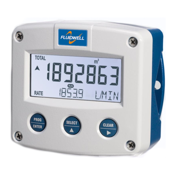
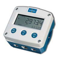
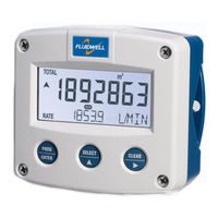
FLOW RATE INDICATOR / TOTALIZER WITH SCALED PULSE OUTPUT
Brand: Fluidwell
|
Category: Measuring Instruments
|
Size: 2 MB
Table of Contents
Advertisement
Fluidwell F014-P User Manual (56 pages)
FLOW RATE INDICATOR / TOTALIZER WITH SCALED PULSE OUTPUT
Brand: Fluidwell
|
Category: Measuring Instruments
|
Size: 3 MB
Table of Contents

Fluidwell F014-P User Manual (56 pages)
FLOW RATE INDICATOR / TOTALIZER WITH SCALED PULSE OUTPUT, Signal input: pulse, NAMUR or coil flowmeter signal, Signal output: one scaled pulse reflecting total, Options: intrinsically safe backlight
Brand: Fluidwell
|
Category: Measuring Instruments
|
Size: 3 MB
Table of Contents
Advertisement

Fluidwell F014-P Manual (44 pages)
FLOWRATE INDICATOR / TOTALIZER WITH SCALED PULSE OUTPUT
Brand: Fluidwell
|
Category: Measuring Instruments
|
Size: 1 MB