Fluidwell F014-A Manuals
Manuals and User Guides for Fluidwell F014-A. We have 2 Fluidwell F014-A manuals available for free PDF download: User Manual, Manual
Fluidwell F014-A Manual (52 pages)
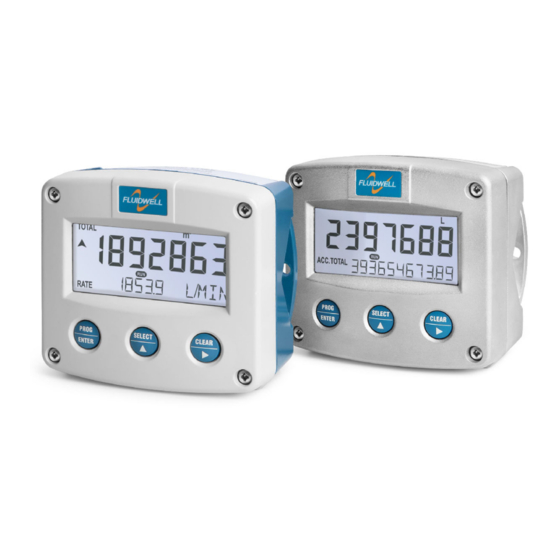
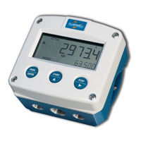
FLOW RATE INDICATOR / TOTALIZER WITH SCALED PULSE OUTPUT
Brand: Fluidwell
|
Category: Measuring Instruments
|
Size: 2 MB
Table of Contents
Advertisement

Fluidwell F014-A User Manual (56 pages)
FLOW RATE INDICATOR / TOTALIZER WITH SCALED PULSE OUTPUT
Brand: Fluidwell
|
Category: Measuring Instruments
|
Size: 3 MB