Sign In
Upload
Manuals
Brands
Festo Manuals
Controller
CMMP-AS-***-M0 Series
Festo CMMP-AS-***-M0 Series Manuals
Manuals and User Guides for Festo CMMP-AS-***-M0 Series. We have
3
Festo CMMP-AS-***-M0 Series manuals available for free PDF download: Manual, Description, Mounting And Installation
Festo CMMP-AS-***-M0 Series Manual (294 pages)
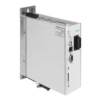
motor controller
Brand:
Festo
| Category:
Controller
| Size: 1 MB
Table of Contents
Table of Contents
3
Instructions on this Documentation
7
Documentation
8
1 Fieldbus Interfaces
9
2 Canopen [X4]
10
Cabling and Pin Assignment
11
Configuration of Canopen Stations on the CMMP-AS-...-M3
13
Setting of the Node Number
14
Setting of the Transmission Rate with DIP Switches
15
Configuration of Canopen Participants on the CMMP-AS-...-M0
16
Setting the Node Number Via Dins and FCT
17
Setting the Protocol (Data Profile) Via Dins or FCT
18
Setting the Physical Units (Factor Group)
19
3 Canopen Access Procedure
20
SDO Access
21
SDO Sequences for Reading and Writing
22
SDO Error Messages
23
Simulation of SDO Access
24
PDO Message
25
Description of the Objects
26
Objects for PDO Parametrisation
29
Activation of Pdos
34
SYNC Message
35
EMERGENCY Message
36
Structure of the EMERGENCY Message
37
Network Management (NMT Service)
39
Bootup
41
Heartbeat (Error Control Protocol)
42
Nodeguarding (Error Control Protocol)
43
Description of the Objects
44
Table of Identifiers
45
4 Ethercat with Coe
46
Installing the Ethercat Interface in the Controller
48
Configuration of Ethercat Participants
50
Canopen Communication Interface
51
New and Revised Objects under Coe
54
Objects Not Supported under Coe
61
Communication Finite State Machine
62
Differences between the Finite State Machines of Canopen and Ethercat
64
SDO Frame
65
PDO Frame
66
Error Control
68
XML Device Description File
69
Receive PDO Configuration in the Rxpdo Node
71
Transmit PDO Configuration in the Txpdo Node
73
Synchronisation (Distributed Clocks)
74
5 Setting Parameters
75
Compatibility Settings
78
Conversion Factors (Factor Group)
80
Output Stage Parameter
90
Current Regulator and Motor Adjustment
96
Speed Control
103
Position Controller (Position Control Function)
105
Setpoint Value Limitation
116
Encoder Adjustments
118
Incremental Encoder Emulation
122
Setpoint/Actual Value Activation
124
Analogue Inputs
127
Digital Inputs and Outputs
129
Limit Switch/Reference Switch
134
Sampling of Positions
137
Brake Activation
140
Device Information
141
Error Management
148
6 Device Control
150
Status Diagram of the Motor Controller (State Machine)
151
Control Word (Controlword)
156
Read-Out of the Motor Controller Status
159
Status Words (Statuswords)
160
Description of the Additional Objects
170
7 Operating Modes
173
Operating Mode Reference Travel (Homing Mode)
175
Description of the Objects
176
Reference Travel Processes
180
Control of Reference Travel
184
Positioning Operating Mode (Profile Position Mode)
186
Description of the Objects
187
Description of Function
190
Synchronous Position Specification (Interpolated Position Mode)
193
Description of Function
199
Speed Adjustment Operating Mode (Profile Velocity Mode)
201
Description of the Objects
203
Speed Ramps
209
Torque Regulation Operating Mode (Profile Torque Mode)
212
Description of the Objects
213
A Technical Appendix
218
B Diagnostic Messages
219
B.2 Error Codes Via Cia 301/402
220
B.3 Diagnostic Messages with Instructions for Fault Clearance
223
Index
282
Advertisement
Festo CMMP-AS-***-M0 Series Mounting And Installation (122 pages)
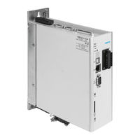
Motor controller
Brand:
Festo
| Category:
Controller
| Size: 0 MB
Table of Contents
Table of Contents
3
Instructions on this Documentation
6
Target Group
6
Product Identification, Versions
6
Service
6
Specified Standards/Directives
6
Documentation
8
1 Safety and Requirements for Product Use
9
Safety
9
Safety Instructions for Commissioning, Repair and De-Commissioning
9
Protection against Electric Shock through Protective Extra-Low Voltage (PELV)
10
Intended Use
10
Requirements for Product Use
11
Transport and Storage Conditions
11
Technical Requirements
11
Qualification of the Specialists (Requirements for the Personnel)
11
Range of Application and Certifications
11
2 Product Overview
13
The Entire System for the CMMP-AS
13
Scope of Delivery
14
Device View
15
3 Mechanical Installation
19
Important Notes
19
Mounting
20
Motor Controller
20
4 Electrical Installation
23
Safety Instructions
23
Allocation of the Plug Connectors
25
Connection: I/O Communication [X1]
29
Plug [X1]
29
Pin Assignment [X1]
29
Use Analogue Inputs as Digital Inputs
30
Connection: Resolver [X2A]
32
Plug [X2A]
32
Pin Assignment [X2A]
32
Connection: Encoder [X2B]
33
Plug [X2B]
33
Pin Assignment [X2B]
33
Connection: CAN Bus [X4]
36
Plug [X4]
36
Pin Assignment [X4]
36
Cmmp-As
37
Connection: Motor [X6]
37
Plug [X6]
37
Pin Assignment [X6]
37
Connection: Voltage Supply [X9]
39
Plug
39
Pin Assignment [X9] - Single-Phase
39
Cmmp-As
39
Pin Assignment [X9] - Triple-Phase
40
Mains Fuse
41
AC Supply
41
Braking Resistor
43
Connection: Incremental Encoder Input [X10]
44
Plug [X10]
44
Pin Assignment [X10]
44
Type and Design of the Cable [X10]
45
Connection Instructions [X10]
45
Connection: Incremental Encoder Output [X11]
45
Plug [X11]
45
Pin Assignment [X11]
45
FCT Interfaces
46
Overview of Interfaces
46
Usb [X19]
46
Ethernet TCP/IP [X18]
47
Connection: I/O Interface for STO [X40]
49
Plug [X40]
49
Pin Assignment [X40]
49
Circuitry with Use of the STO Safety Function [X40]
49
Circuitry Without Use of the STO Safety Function [X40]
49
Instructions on Safe and EMC-Compliant Installation
51
Explanations and Terms
51
General Remarks on EMC
51
EMC Areas: First and Second Environment
52
EMC-Compliant Wiring
53
Operation with Long Motor Cables
55
ESD Protection
55
5 Commissioning
56
General Connection Instructions
56
Tools / Material
56
Connecting the Motor
56
Connect Motor Controller CMMP-AS
57
Connecting a PC
57
Check Operating Status
58
6 Service Functions and Diagnostic Messages
59
Protective and Service Functions
59
Overview
59
Phases and Mains Failure Detection
59
Overload Current and Short-Circuit Monitoring
59
Overvoltage Monitoring for the Intermediate Circuit
59
Temperature Monitoring for the Heat Sink
59
Monitoring of the Motor
60
I2T Monitoring
60
Power Monitoring for the Brake Chopper
60
Commissioning Status
61
Rapid Discharge of the Intermediate Circuit
61
Detection of Faults in Conjunction with the Functional Safety Engineering
61
Operating Mode and Diagnostic Messages
61
Operation and Display Components
61
7-Segment Display
62
Acknowledgement of Error Messages
63
Diagnostic Messages
63
7 Maintenance, Care, Repair and Replacement
64
Maintenance and Care
64
Repair
64
Replacement and Disposal
64
Dismounting and Installation
64
Disposal
64
A Technical Appendix
65
Technical Data CMMP-AS
65
Interfaces
73
Supported Encoders
79
B Diagnostic Messages
81
Explanations of the Diagnostic Messages
81
Diagnostic Messages with Instructions for Fault Clearance
82
Index
121
Festo CMMP-AS-***-M0 Series Description (122 pages)
Motor controller
Brand:
Festo
| Category:
Controller
| Size: 0 MB
Table of Contents
Table of Contents
3
1 Safety and Requirements for Product Use
8
Safety
8
Safety Instructions for Commissioning, Repair and De-Commissioning
8
Protection against Electric Shock through Protective Extra-Low Voltage (PELV)
9
Designated Use
9
Prerequisites for Use
10
Technical Requirements
10
Qualification of the Specialists (Requirements for the Personnel)
10
Range of Application and Certifications
10
2 Operating Modes and Functions
11
Overview
11
3 Control Interfaces
12
Overview of Interfaces
12
4 Fieldbus Options
13
Supported Fieldbuses
13
Required I/O Connection for Fieldbus Control
14
5 Service
16
Supported Functions
16
Memory Card
16
Load Firmware Via Memory Card
17
Load Parameter Set from Memory Card
17
Ethernet (TFTP)
18
Load Firmware Via Ethernet
18
Load Parameter Set Via Ethernet
19
Save Parameter Set Via Ethernet
19
Cmmp-As
20
6 Functions
20
Position Controller
20
Basic Principles of the Position Controller
20
Record Selection through I/O
25
Start of the Record Selection
25
Stop of the Record Selection through "Digital Halt
25
Record Selection with Record Continuation
25
Modulo Positioning
27
Homing
30
Homing Methods
30
Homing - Options
36
Homing Parameters
37
Secure Zero Point Shift
37
Homing Via I/O
38
Timing Diagrams
39
Jog Mode
42
Function
42
Process
42
Jog Mode Parameters
43
Teach-In Function
46
Setpoint Specification
47
Analogue Setpoint
47
Digital Nominal Value
48
Cmmp-As
48
Master-Slave
52
Flying Saw
52
Scope of Functions for Cam Discs (CAM)
53
Second Measuring System
54
Technology
54
Example, Toothed Belt Axis
55
Example, Spindle Axis
55
Function in the Motor Controller
55
Inclusion of a Second Displacement Encoder
56
2Nd Measuring System at the Incremental Encoder Input [X10]
56
Egc
57
2Nd Measuring System at Input [X2A]
58
Commissioning
58
Additional Functions
59
Encoder Emulation
59
Brake Control and Automatic Brake
60
Position Trigger
62
Inputs for Option "Flying Measurement
63
Software Limit Switch
63
Input for Digital Halt
64
Digital and Analogue Inputs/Outputs [X1]
64
Supported Encoder Systems
72
7 Dynamic Response
74
PFC for Increased Intermediate Circuit Voltage
74
Switch-On Behaviour
74
Behaviour under Normal Operation and Control Properties
75
Extended Sine Modulation for Increased Output Voltage
76
Variable Cycle Times, Current, Speed and Position Controller
76
8 Service Functions and Diagnostic Messages
77
Protective and Service Functions
77
Overview
77
Phases and Mains Failure Detection with 3-Phase Motor Controllers
77
Overload Current and Short-Circuit Monitoring
77
Overvoltage Monitoring for the Intermediate Circuit
78
Temperature Monitoring for the Heat Sink
78
Monitoring of the Motor
78
I 2 T Monitoring
78
Power Monitoring for the Brake Chopper
78
Commissioning Status
79
Rapid Discharge of the Intermediate Circuit
79
Operating Mode and Error Messages
79
Operating Mode and Error Display
79
7-Segments Display
80
Acknowledgement of Error Messages
81
Diagnostic Messages
81
A Diagnostic Messages
82
Explanations of the Diagnostic Messages
82
Diagnostic Messages with Instructions for Troubleshooting
83
Advertisement
Advertisement
Related Products
Festo CMMP-AS-***-M3 Series
Festo CMMP-AS-C2-3A
Festo CMMP-AS-C5-3A
Festo CMMP-AS-C5-3A-M0
Festo CMMP-AS-C2-3A-M0
Festo CMMP-AS-C5-11A-P3-M0
Festo CMMP-AS
Festo CMMP-AS-C2-3A-M3
Festo CMMP-AS-C5-3A-M3
Festo CMMP-AS-C5-11A-P3-M3
Festo Categories
Industrial Equipment
Control Unit
Controller
Touch terminals
DC Drives
More Festo Manuals
Login
Sign In
OR
Sign in with Facebook
Sign in with Google
Upload manual
Upload from disk
Upload from URL