Sign In
Upload
Manuals
Brands
FATEK Manuals
Controller
M Series
FATEK M Series Manuals
Manuals and User Guides for FATEK M Series. We have
7
FATEK M Series manuals available for free PDF download: Instructions & User's Manual, User Manual, Hardware User Manual
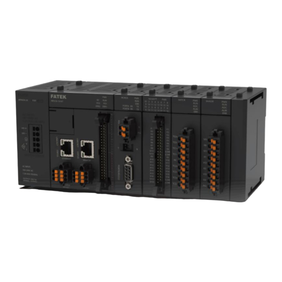
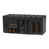
FATEK M Series Instructions & User's Manual (625 pages)
Brand:
FATEK
| Category:
Controller
| Size: 14 MB
Table of Contents
Table of Contents
2
Precautions on Using the Product
5
Chapter 1 PLC Ladder Diagram and the Coding Rules of Mnemonic
7
The Operation Principle of Ladder Diagram
8
Combination Logic
8
Sequential Logic
10
Differences between Conventional and Plc Ladder Diagram
12
Ladder Diagram Structure and Terminolog
14
Chapter 2 Configuration of Memory, Single Point (Digital) and Register in PLC
19
M PLC Memory Configuration
21
Digital and Register Configuration
22
CPU Special Relay Details
25
CPU Special Registers Details
33
Motion Special Relay Details
58
Motion Special Register Details
63
Chapter 3 M PLC Instruction Lists
65
Sequential Instructions
66
Function Instructions
69
Chapter 4 Sequential Instruction
83
Element Description
83
Characteristics of A,B,TU and TD Contacts
83
OPEN and SHORT Contact
85
Output Coil and Inverse Output Coil
86
Retentive Output Coil
86
Set Coil and Reset Coil
87
Chapter 5 Description of Function Instructions
88
The Format of Function Instructions
89
Input Control
90
Instruction Number and Derivative Instructions
91
Operand
93
Functions Output (FO)
96
Use W Prefix for Word and Bit Access Transformation
97
Numbering System
98
Binary Values and the Terms
98
M PLC Digit
99
Value Range
99
Display of Values (Please Skip this Section for Beginners)
99
Use Index Register (Xr) for Indirect Addressing
101
Index Register (P0~P9) Introduction
101
Indirect Addressing Program Example
102
Representation of Negative Number (Beginners Should Skip this Section)
105
Representation of Floating Point Number (Beginners Should Skip this Section)
105
Overflow and Underflow of Increment (+1) or Decreme Nt (-1) Instruction
107
Carry and Borrow in Addition/Subtraction
108
Chapter 6. Basic Function Instruction
113
Timer(T)
113
Counter(C)
116
Set(S)
120
Rst(R)
123
Master Control(MC)
126
Master Control End(Mce)
129
Skip(Skp)
130
Skip End(Skpe)
132
Differential up (Difu)
133
Differential down(Difd)
135
Bit Shift(Bshf)
136
Up/Down Counter(Udctr)
138
Move(Mov)
140
Move Inverse(Mov/)
142
Toggle Switch(Togg)
144
Fast Addition F
145
Fast Subtraction F
148
Addition
151
Subtraction
153
Multiplication
155
Division
158
Increment(+1
161
Decrememt(-1
163
Compare(Cmp)
165
Logical and(And)
167
Logical(Or)
169
Bin→Bcd Conversion
171
Bcd→Bin Conversion
173
Modulo(Mod)
175
Chapter 7. Advanced Function Instructions
177
Arithmetical Operation Instructions(Fun24~33
182
Summation of Block Data(Sum
182
Average of Block Data (MEAN)
185
Take the Negative Value (NEGATION)
187
Take the Absolute Value (ABSOLUTE)
189
Linear Conversion (LCNV)
191
Multiple Linear Conversion (MLC)
202
Logical Operation Instructions (Fun35~36)
214
Exclusive or (Xor)
214
Exclusive nor (Xnr)
216
Comparison Instructions (Fun37)
218
Zone Compare (Zncmp)
218
Data Movement Instructions(Fun40~50
220
Bit Read (Bitrd)
220
Bit Write (Bitwr)
222
Bit Move (Bitmv)
224
Nibble Move (Nbmv)
226
Byte Move (Bymv)
228
Exchange (Xchg)
231
Byte Swap (Swap)
233
Shifting/Rotating Instructions (Fun51~54)
235
Shift Left (Shfl)
235
Shift Right (Shfr)
238
Rotate Left (Rotl)
240
Rotate Right (Rotr)
242
Code Conversion Instructions (Fun55~64)
244
Inary-Code to Gray-Code Conversion (B→G)
244
Gray-Code to Binary-Code Conversion (G→B)
246
Hour:minute:second→Second
248
Second→Hour:minute:second
251
Conversion of Ascii Code to Hexadecimal Value (Ascii→Hex)
254
Conversion of Hexadecimal Value to Ascii Code (Hex→Ascii)
257
Flow Control Instructions II (Fun22、Fun65~71)
262
Break
262
Label (Lbl)
264
Jump (Jmp)
267
Funtion Block Label
269
Funtion Block Jump
272
Call
274
Return from Subroutine (Rts)
277
Return from Interrupt (Rti)
278
For
281
Next
283
Program End
284
I/O Instructions (Fun74~86)
286
Immediate I/O Refresh (Imdio)
286
PID Control (Fun30,Fun38, Fun99)
288
General PID Operation (Main Unit)
288
General-Purpose PID 2 Instruction
298
PID Temperature Control Instruction 2 (TPCTL 2)
301
Cumulateive Timer Instruction (Fun87~89)
303
ACCUMULATIVE TIMER (10Ms, 100Ms, 1S)
303
Watchdog Timer Instructions (Fun90~91)
307
Watchdog Timer (WDT)
307
Reset Watchdog Timer (Rswdt)
308
High Counting/Timing Instruction (Fun92~93)
310
Hareware High Speed Counter Current Value Access
310
Hardware High Speed Counter Current Value and Preset Value Writing
312
Slow Up/Slow down (Fun95~98)
316
Tracking Type Ramp Function for D/A Output
316
Register to Table Move
324
Block Table Move (Bt_M)
330
Register to Table Search
332
First Time
345
Second Time
345
Queue
346
Stack
349
Block Compare (Drum)
352
Data Sorting (Sorting)
356
Zone Write
358
Matrix Instruction (Fun120~130)
362
Matrix and
362
Matrix or
365
Matrix Exclusive or
368
Matrix Enclusive nor
371
Matrix Inverse
374
Matrix Bit Shift
376
Matrix Bit Rotate
379
NC Positioning Instruction (Fun137~143)
384
Ica
384
Icf
386
Hspwm
388
High Speed Pulse Output Instruction
390
Positioning Program Parameter Setting Command (MPARA)
392
Stop the Hspso Pulse Output (Psoff)
401
Convert the Current Pulse Value to Display Value(PSCNV)
402
Enable/Disable (Fun145~146)
406
Enable Control of the Interrupt and Peripheral
406
Disable Control of the Interrupt and Peripheral
410
NC Positioning Instructions II (Fun147~149)
412
Multi-Axis High Speed Pulse Output
412
Manual Pulse Generator for Positioning
414
Arc High Speed Pulse Output
422
Communication Instruction (Fun150~156)
424
Modbus Master Instruction(M-Bus)
424
Communication Link Instruction (Clink)
426
Network Active Communication (NCR)
428
Cmctl
430
Data Movement Instructions (Fun160~162)
433
Read/Write File Register
433
Write SD Card (WR-MP)
436
Read SD Card (RD-MP)
440
In Line Comparison Instruction (Fun170~175)
443
Equal to Compare
443
Greater than Compare
446
Less than Compare
448
Not Equal to Compare
451
Greater than or Equal to Compare
453
Less than or Equal to Compare
455
Motion Control Instructions
457
Running Motion Process (Mfflowstart)
457
Stop All Motion Processes (Mfsysstop)
458
Home Re-Set (Mfhome)
459
Position Control (Mfpointmov)
461
JOG (Mfjog)
463
Change Motion Control Parameters (Mfchgtbprm)
466
Pause Motion Flow (Mfflowpause)
468
Resume Motion Process (Mfflowresume)
470
Motion Process Halt (Mfflowhalt)
472
Reset Motion Alarm (Mfsysrstalm)
474
Motion Process Terminate (Mfflowstop)
476
Servo Initialization (Mfsysinit)
478
Recipe Reading (Mfsysrcpr)
480
Motion Control Recipe Writing (Mfsysrcpw)
495
Cam Read (Mfsyscamr)
507
Cam Write (Mfsyscamw)
509
Handwheel (Mfgearmpg)
511
Velocity Control Mode (Mfvelctl)
515
Torque Control Mode (Mftorqctl)
517
Cam Generate (Mfsyscamgen)
519
Axis Movement (Mfaxmov)
522
Mapping Table Setting (Mfmaptbprm)
526
Real Axis to Virtual Axis (Mfsyssetvirt)
528
Ethercat SDO Read (MFSDOR)
529
Ethercat SDO Write (MFSDOW)
531
Linear Interpolation (Mfaxlmov)
534
Arc Interpolation (Mfaxcirmov)
538
Path Movement (Mfpathmov)
544
Other Instructions (Fun115, Fun258)
547
Data Buffering (DBUF)
547
Tare Weight Deduction Command
550
Tare Weight Offset Command
552
Floating Point Instructions (Fun200~220)
554
Conversion of Integer to Floating Point Number
554
Conversion of Floating Point Number to Integer
556
Floating Point Number Addition
558
Floating Point Number Subtraction
560
Floating Point Number Multiplication
562
Floating Point Number Dividion
564
Floating Point Number Compare
566
Floating Point Number Zone Compare
568
Floating Point Number Square Root
570
Sin Trigonometric Instruction
572
Cos Trigonometric Instruction
574
Tan Trigonometric Instruction
576
Change Sign of the Floating Point Number
578
Floating Point Number Absolute Value
580
Floating Point Arc Sine Function
582
Floating Point Arc Cosine Function
584
Chapter 8. Step Instruction Description
586
The Operation Principle of Step Ladder Diagram
588
Basic Formation of Step Ladder Diagram
589
Introduction of Step Instruction:stp、From、To、Stpend
594
Notes for Writing a Step Ladder Diagram
613
Application Examples
617
Syntax Check Error Codes for Step Instruction
624
Advertisement
FATEK M Series User Manual (324 pages)
PLC Motion Programmable Controller
Brand:
FATEK
| Category:
Controller
| Size: 13 MB
Table of Contents
Dimensions and Weight
8
Performance Data
8
Amendment Record
9
Origin Return
133
Speed Control
135
Torque Control
137
Linear Interpolation
165
Precautions for Use
187
HOME Return
188
Jog Mode
216
Probe Mode
290
FATEK M Series User Manual (252 pages)
Brand:
FATEK
| Category:
Controller
| Size: 10 MB
Table of Contents
Table of Contents
2
Chapter 1 Summary of M-PLC Motion Control Unit
9
Motion Unit Function Diagram
10
Axis Control Function and Reference
11
Axis Control Function and Reference
12
Action before M-PLC Positioning Control
15
Chapter 2 Motion Parameters and Status (Special Register and Relay)
16
Motion Flow_Special Relay & Register
18
Motion Control_Special Relay & Register
19
Chapter 3 Ethercat Function and Configuration
23
Chapter 4 Axis Parameters and Setting
26
Motion Network Setting
27
Motion Axis Parameter Setting
28
Chapter 5 Point Table and Point Parameter
33
Motion Point Setting Interface
34
Point Preview Picture
39
Chapter 6 Ladder Motion Commands
41
Fun187 System Initialization (ME_SYSINIT)
43
Fun177 Motion System Emergency Stop (ME_SYSSTOP)
46
Fun182 Pause Motion Flow (ME_PAUSE)
47
Fun183 Resume Motion Flow (ME_RESUME)
49
Fun179 Position Control (ME_POS)
50
Fun180 JOG Control (ME_JOG)
52
Fun178 HOME Return (ME_HOME)
54
Fun185 Reset Motion Error Alarm (ME_RSTALM)
56
Fun181 Change Motion Control Parameter
58
Fun188 Read Motion Control Recipe
63
Fun189 Write Motion Control Recipe
69
Fun191 Read Motion Control Cam
75
Fun192 Write Motion Control Cam
77
Fun193 Ethercat Handwheel (ME_GEAR_IN)
79
Fun194 Velocity Control (ME_VEL_CTL)
81
Fun195 Torque Control (ME_TOR_CTL)
83
Fun197 單軸定位 (ME_AXI_MOV)
85
Fun196 Generate Cam (ME_CAM_GEN)
87
Fun198 Set Mapping Table (ME_SET_MAP)
89
Torque Control
100
Standby
101
Subroutine
102
Goto
103
Sync
104
Calculate
105
End
108
Using M-PLC Position Control Flow
110
Using Ladder Position Control
111
Using Motion Flow Positioning
122
Description of Multi-Axis Interpolation
125
Linear Interpolation
125
Arc Interpolation
125
Spiral Interpolation
125
What Is Synchronous Control
189
Synchronous Parameter Setting Group
190
Introduction of Synchronous Parameter
191
Synchronous Cam Setting
204
Characteristics of Cam Profile
208
Advertisement
FATEK M Series User Manual (141 pages)
Programmable Controller Expansion Module
Brand:
FATEK
| Category:
Controller
| Size: 5 MB
Table of Contents
Expansion of M-Series Plc
17
Table of Contents
2
Chapter 1 List of Expansion Modules
14
Chapter 2 Expansion of M-Series PLC
17
I/O Expansion Specifications
18
Digital I/O Expansion and I/O Channel Numbering
19
Digital I/O Expansion and I/O Numbering
19
Analog I/O Expansion and I/O Numbering
21
Expansion Module Configuration Settings
24
Expansion Module Firmware Update
26
Chapter 3 Installation and Wiring
27
Environmental Specifications
28
Installation Precautions
29
Power Wiring, Power Consumption Calculation, and Power Sequence Requirements
37
Specifications and Wiring of AC Power Module
38
Chapter 4 Power Wiring, Power Consumption Calculation, and Power Sequence Requirements
39
Maximum Current Consumption of Expansion Module
41
Calculation Example of Power Capacity
43
Requirement of Power Sequence in CPU Module & Expansion Module
44
Chapter 5 Digital Input Circuit
45
Digital Input Circuit Specifications
46
24VDC Single-End Input Circuit and Wiring for SINK/SOURCE Input
47
Digital Output (Do) Circuit
49
Chapter 6 Digital Output Circuit
49
Digital Output Circuit Specifications
50
Single-End Output Circuit
51
Speed up the Single-End Transistor Output Circuit
54
Speed up the Single-End Transistor Output Circuit (High/ Medium)
54
Output Device Protection and Noise Suppression in DO Circuit
55
Chapter 7 Left Side Expansion Module Specifications
58
Power Module Specifications
59
Chapter 8 Right Side High Speed Expansion Module Specifications
63
High Speed Communication Expansion Module Specifications
64
Right Side Expansion Module Specifications
68
Chapter 9 Right Side Expansion Module Specifications
68
Digital Input Expansion Module Specifications
69
Right Side Expansion Module
69
Specifications
69
Digital Output Expansion Module Specifications
72
Digital Input /Output Combo Expansion Module Specifications
77
Analog Input Expansion Module Specifications
82
Analog Output Expansion Module Specifications
88
Analog Input/Output Combo Expansion Module Specifications
94
Temperature Expansion Module Specifications
98
Temperature Combo Expansion Module Specifications
102
Load Cell Expansion Module Specifications
105
Chapter 10 Left Side Expansion Dimensions
111
Power Module Dimensions
112
Chapter 11 Right Side High Speed Expansion Dimensions
114
High Speed Communication Expansion Module Dimensions
115
Right Side Expansion Dimensions
117
Chapter 12 Right Side Expansion Dimensions
117
Digital Input Expansion Module Dimensions
118
Digital Output Expansion Module Dimensions
119
Digital Input/Output Combo Expansion Module Dimensions
121
Analog Input Expansion Module Dimensions
122
Analog Output Expansion Module Dimensions
124
Analog Input/Output Combo Expansion Module Dimensions
126
Temperature Expansion Module Dimensions
127
Temperature Combo Expansion Module Dimensions
129
Load Cell Expansion Module Dimensions
130
End Module Cover Dimensions
132
Chapter 13 Expansion Module Troubleshooting
133
Digital Input Expansion Module Troubleshooting
134
Digital Output Expansion Module Troubleshooting
134
Digital Input/Output Combo Expansion Module Troubleshooting
134
Analog Input Expansion Module Troubleshooting
134
Analog Output Expansion Module Troubleshooting
134
Analog Input/Output Expansion Module Troubleshooting
134
Temperature Input Expansion Module Troubleshooting
135
Temperature Combo Expansion Module Troubleshooting
135
Load Cell Expansion Module Troubleshooting
135
Chapter 14 Repairs and Maintenance
136
Precautions
137
Daily Maintenance
138
Regular Maintenance
139
FATEK M Series Hardware User Manual (113 pages)
PLC CPU Module
Brand:
FATEK
| Category:
Control Unit
| Size: 6 MB
Table of Contents
Table of Contents
2
Warranty Service
4
Service de Garantie
5
Precautions on Using the Product
6
Dimensions and Weight
8
Performance Data
8
Avis de Non-Responsabilité
9
Precautions for Safety
10
Précautions de Sécurité
13
Precautions for Use
16
Installation
16
Précautions D'utilisation
19
Overview
23
Overview
24
Manuals Used
28
Product Line
29
Product Features
30
Composition of M-Series PLC Single Model System Types
32
System Configuration
33
Basic System Configuration
34
Precautions for System Configuration
35
Measurement Module
35
Motion Control Configuration
38
Configuration in Connecting with System Bus
39
Connection Configuration of MQ Compact PLC
40
Uperlogic
41
Connection Method
42
Connection through USB
42
CPU Interface and Peripheral Functions
44
Instructions for CPU Panel Interface and Functions
45
RUN/STOP Changeover Switch
48
Layout Diagram of Ethernet, Ethercat Pin
50
Layout Diagram of RS485, AI Pin
51
Display Inducator of LED Status
52
CPU Module Push in Terminal Block Layout
54
Memory Card
56
Installing Microsd Card
56
Specification
57
Series PLC Specifications
60
General Specifications
60
Memory Card
61
CPU Advanced Specifications
61
Digital Input (DI) Circuit
67
Digital Output (DO) Circuit
69
Analog Input Specifications
73
Dimensions of CPU Module
74
Specifications and Functions
88
Hardware Installation and Wiring
91
Module Assembly
94
Power Wiring
100
AC Power Wiring
101
Maintenance and Inspections
107
Daily Maintenance
110
Regular Maintenance Items
111
Revision History
113
FATEK M Series User Manual (117 pages)
Structured Language ST
Brand:
FATEK
| Category:
Controller
| Size: 4 MB
Table of Contents
Table of Contents
2
Preface
4
Precautions on Using the Product
5
Precautions for Safety
7
Precautions for Use
10
Installation
10
Understand Structured Language ST
14
Features of ST Language
15
Adding ST Language Program
17
User Interface of Uperlogic ST
20
Interface Overview
21
Supportive Keyboard Instructions
24
Sytem Mode
25
Syntax Check
26
Mouse Hover Prompt
28
Add Observed Variables
29
Quick Mouse and Keyboard Operations
30
Structured Text Color Adjustment
31
Quick Call/Create Table
32
Basic Program Structure of Uperlogic ST
33
Introduction
34
Statement
36
Expression
39
Operand and Operator
44
Comment
49
Flow Control and Loop
50
Variables and Data Type
58
Floating Point
61
Using PLC Register and Memory
66
Calling System Built-In Functions
67
Functions with Multiple Calling Modes
71
Multi-Cycle Instruction
72
Enable/Disable Interrupt and Special Instructions
75
Variable Names with Special Meanings
84
Calling FCM Function
88
Function Notes
90
ST Editing Environment Support Function List
91
Name Comparison between Ladder and ST Editing Environment Instructions
92
Functions with Multiple Calling Modes
98
FATEK M Series User Manual (62 pages)
Programmable Controller
Brand:
FATEK
| Category:
Controller
| Size: 2 MB
Table of Contents
Precautions on Using the Product
5
Precautions for Safety
7
Precautions for Use
10
Installation
10
Interface Overview
20
Advertisement
Related Products
FATEK M04AD
FATEK M04ADR
FATEK M04DA
FATEK M04DAR
FATEK M0202AH
FATEK M04TC
FATEK M04TCR
FATEK M0202TH
FATEK M02LC
FATEK M02LCR
FATEK Categories
Controller
Control Unit
Industrial Equipment
Network Hardware
Recording Equipment
More FATEK Manuals
Login
Sign In
OR
Sign in with Facebook
Sign in with Google
Upload manual
Upload from disk
Upload from URL