Sign In
Upload
Manuals
Brands
Eurotherm Manuals
Temperature Controller
2216e
Eurotherm 2216e Manuals
Manuals and User Guides for Eurotherm 2216e. We have
3
Eurotherm 2216e manuals available for free PDF download: Installation And Operation Handbook, Installation Instructions
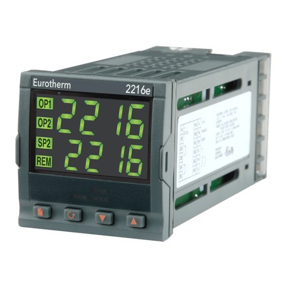
Eurotherm 2216e Installation And Operation Handbook (120 pages)
Brand:
Eurotherm
| Category:
Temperature Controller
| Size: 0 MB
Table of Contents
Table of Contents
1
Issue 2.0 Oct
6
Chapter 1 OPERATION
7
Front Panel Layout
8
Getting Started
10
Viewing the Process Value and Setpoint
10
To Adjust the Setpoint
10
Viewing the Display Units
11
Use of the "SCROLL" Button
11
Use of the 'PAGE' Button
12
Parameter Lists
13
Manual or Automatic Control
14
Selecting Auto/Manual Operation
14
How to Manually Adjust Output Power
15
Setpoint 1 or Setpoint 2
16
To Select Setpoint 1 or Setpoint 2
16
Ramp Dwell Function
17
To Set up a Ramp/Time Program
17
To Run the Program
18
Power Failure During Program Run
18
Location of Parameters - Block Diagram
19
NAVIGATION DIAGRAM (Part A)
20
Navigation Diagram (Part B)
21
Parameter Tables
22
HOME Display
22
Alarm List
23
Autotune List
23
PID List
24
Setpoint List
25
Input List
26
On/Off List
26
Output List
27
Communications List
27
Access List
27
Alarms
28
Types of Alarm Used in the 2200
28
Alarm Relay Output
29
Setting Alarm Levels
30
Alarm Indication and Acknowledgement
31
Diagnostic Alarms
32
Chapter 2 INSTALLATION
35
Instrument Layout
36
Outline Dimensions Model 2216E
37
Introduction
38
Controller Labels
38
Mechanical Installation
38
Unplugging and Plugging-In the Controller
38
Wiring
39
Wire Sizes
39
Wiring Connections
39
Sensor Input Connections
40
Outputs 1 and 2 Connections
40
Pds Modes
41
Snubbers
41
Typical Single Loop Wiring Diagram
42
Communication Connections
43
Wiring of EIA-485 Serial Communication Links
44
Devicenet Wiring to Series 2200E Controllers
45
Devicenet Terminal Functions
45
Wiring Interconnections for Devicenet Communications
46
Chapter 3 ACCESS LEVELS
47
The Different Access Levels
48
Selecting an Access Level
49
Level Selection
50
Returning to Operator Level
51
Edit Level
51
Setting Operator Access to a Parameter
51
Hiding or Revealing a Complete List
52
Promoting a Parameter
52
Chapter 4 TUNING
53
Chapter 4 TUNING
54
What Is Tuning
54
Automatic Tuning
55
Heating and Cooling Output Cycle Times
55
How to Tune
56
Typical Automatic Tuning Cycle
57
Calculation of the Cutback Values
57
Manual Tuning
58
Setting the Cutback Values
59
Integrating Action and Manual Reset
60
Automatic Droop Compensation (Adc)
60
Chapter 5 CONFIGURATION
61
Selecting Configuration Level
62
Selecting a Configuration Parameter
63
Leaving Configuration Level
63
Steps Involved in Configuring a Controller
63
Navigation Diagram (Part A)
64
Navigation Diagram (Part B)
65
Configuration Parameter Tables
66
Configuration of Digital Communications
74
To Configure the Function and Baud Rate
74
To Set Instrument Address
75
Devicenet
75
The EDS File
75
ODVA Compliance
75
Chapter 6 USER CALIBRATION
77
Chapter 6 USER CALIBRATION
78
What Is the Purpose of User Calibration
78
User Calibration Enable
79
Single Point Calibration
80
Two Point Calibration
81
Calibration Points and Calibration Offsets
82
Chapter 7 ALARM CONFIGURATION
83
Definition of Alarms and Events
84
Types of Alarms
84
Digital Output Functions
86
Step1 - Configuring the Four 'Soft' Alarms
87
Step 2 - Attaching an Alarm to a Physical Output
88
Step 3 - Grouping Alarms on a Single Output
89
Step 4 - Removing Alarms from an Output
89
Chapter 8 MOTORISED VALVE CONTROL
91
Chapter 8 MOTORISED VALVE CONTROL
92
Commissioning the Motorised Valve Controller
92
Adjusting the Minimum On-Time ' .6D
92
Parameters for Motorised Valve Control
92
Motorised Valve Applications
93
Auto Tuning
93
Valve Positioner Set-Up Table
93
Chapter 9 Load Current Monitoring and Diagnostics
95
Load Current Monitoring and Diagnostics
96
Example Wiring Diagram (Mode 1 & 2 Operation)
97
Operation
98
To Read Load Current (Mode 2 Only)
98
To Display Load Current Continuously in the Lower Readout
98
Display Modes
98
Only)
98
How Heater Alarms Are Displayed
99
To Set the Alarm Trip Levels
100
Relay Outputs
100
To Configure Pds Load Current Diagnostics
101
To Configure the Logic Module for PDS Modes 1 or 2
101
To Configure Low and High Current Trip Alarms
102
To Attach Soft Alarms to a Relay Output
103
The Scaling Factor
104
To Adjust the Scaling Factor
104
10 Chapter 10 RETRANSMISSION
106
What Is Retransmission
106
To Configure Retransmission
107
Scaling Retransmitted Output Signals
108
To Range Retransmitted Output 0
108
To Range Retransmitted Error 55
109
Appendix A UNDERSTANDING the ORDERING CODE
111
Appendix B SAFETY and EMC INFORMATION
115
Installation Safety Requirements
116
Advertisement
Eurotherm 2216e Installation And Operation Handbook (112 pages)
Temperature controllers
Brand:
Eurotherm
| Category:
Temperature Controller
| Size: 1 MB
Table of Contents
Table of Contents
3
Chapter 1 OPERATION
7
Front Panel Layout
7
Getting Started
9
Viewing the Process Value and Setpoint
9
To Adjust the Setpoint
9
Viewing the Display Units
10
Use of the "SCROLL" Button
10
Use of the 'PAGE' Button
11
Parameter Lists
12
Manual or Automatic Control
13
Selecting Auto/Manual Operation
13
How to Manually Adjust Output Power
14
Setpoint 1 or Setpoint 2
15
To Select Setpoint 1 or Setpoint 2
15
Ramp Dwell Function
16
To Set up a Ramp/Time Program
16
To Run the Program
17
Power Failure During Program Run
17
Location of Parameters - Block Diagram
18
NAVIGATION DIAGRAM (Part A)
19
Parameter Tables
21
HOME Display
21
Alarm List
22
Autotune List
23
PID List
23
Setpoint List
24
Input List
25
On/Off List
25
Output List
26
Communications List
26
Access List
26
Alarms
27
Types of Alarm Used in the 2200
27
Alarm Relay Output
28
Setting Alarm Levels
29
Alarm Indication and Acknowledgement
30
Diagnostic Alarms
31
Chapter 2 INSTALLATION
33
Instrument Layout
33
Outline Dimensions Model 2216E
34
Introduction
35
Controller Labels
35
Mechanical Installation
35
Unplugging and Plugging-In the Controller
35
Wiring
36
Wire Sizes
36
Wiring Connections
36
Sensor Input Connections
37
Outputs 1 and 2 Connections
37
Pds Modes
38
Snubbers
38
Typical Single Loop Wiring Diagram
39
Logic Drive Fan out
40
Communication Connections
40
Wiring of EIA-485 Serial Communication Links
41
Devicenet Wiring to Series 2200E Controllers
42
Devicenet Terminal Functions
42
Wiring Interconnections for Devicenet Communications
43
Chapter 3 ACCESS LEVELS
45
The Different Access Levels
45
Selecting an Access Level
46
Access List Header
46
Password Entry
46
Level Selection
47
Configuration Password
47
Configuration Level
47
Returning to Operator Level
48
Edit Level
48
Setting Operator Access to a Parameter
48
Hiding or Revealing a Complete List
48
Promoting a Parameter
48
Chapter 4 TUNING
49
What Is Tuning
49
Automatic Tuning
50
Heating and Cooling Output Cycle Times
50
How to Tune
51
Typical Automatic Tuning Cycle
51
Calculation of the Cutback Values
51
Manual Tuning
52
Setting the Cutback Values
53
Integrating Action and Manual Reset
54
Automatic Droop Compensation (Adc)
54
Chapter 5 CONFIGURATION
55
Selecting Configuration Level
56
Selecting a Configuration Parameter
57
Leaving Configuration Level
57
Steps Involved in Configuring a Controller
57
Navigation Diagram (PART A)
58
Navigation Diagram (PART B)
59
Configuration PARAMETER TABLES
60
CONFIGURATION of Digital Communications
68
To Configure the Function, and Baud Rate
68
To Set Instrument Address
69
Devicenet
69
The EDS File
69
ODVA Compliance
69
Chapter 6 USER CALIBRATION
71
What Is the Purpose of User Calibration
71
User Calibration Enable
72
Single Point Calibration
73
Two Point Calibration
74
Calibration Points and Calibration Offsets
75
Chapter 7 ALARM CONFIGURATION
77
Definition of Alarms and Events
77
Types of Alarms
77
Digital Output Functions
79
Step1 - Configuring the Four 'Soft' Alarms
80
Step 2 - Attaching an Alarm to a Physical Output
81
Step 3 - Grouping Alarms on a Single Output
82
Step 4 - Removing Alarms from an Output
82
Chapter 8 MOTORISED VALVE CONTROL
83
Parameters for Motorised Valve Control
83
Commissioning the Motorised Valve Controller
83
Adjusting the Minimum On-Time 'Ont.h
83
Motorised Valve Applications
84
Auto Tuning
84
Valve Positioner Set-Up Table
84
Chapter 9 LOAD CURRENT MONITORING and DIAGNOSTICS
85
Load Current Monitoring and Diagnostics
85
Example Wiring Diagram (Mode 1 & 2 Operation)
86
Operation
87
To Read Load Current (Mode 2 Only)
87
To Display Load Current Continuously in the Lower Readout (Mode 2 Only)
87
Display Modes
87
How Heater Alarms Are Displayed
88
To Set the Alarm Trip Levels
89
Relay Outputs
89
To Configure Pds Load Current Diagnostics
90
To Configure the Logic Module for PDS Modes 1 or 2
90
To Configure Low and High Current Trip Alarms
91
To Attach Soft Alarms to a Relay Output
92
The Scaling Factor
93
To Adjust the Scaling Factor
93
Chapter 10 RETRANSMISSION
95
What Is Retransmission
95
To Configure Retransmission
96
Scaling Retransmitted Output Signals
97
To Range Retransmitted Output OP
97
To Range Retransmitted Setpoint SP or Process Variable PV
98
To Range Retransmitted Error Err
98
Appendix A UNDERSTANDING the ORDERING CODE
99
Appendix B SAFETY and EMC INFORMATION
103
Installation Safety Requirements
104
Safety Symbols
104
Control Functions
108
Appendix C Rohs
109
Eurotherm 2216e Installation Instructions (4 pages)
2200e Series
Brand:
Eurotherm
| Category:
Controller
| Size: 0 MB
Table of Contents
To Remove the Controller from Its Sleeve
1
Wiring
1
Wire Sizes
1
Installation
1
Panel Cutout
1
Safety and EMC Information
2
Parameter Descriptions
2
General Notes about Relays and Inductive Loads
3
PDS (Pulse Density Signalling)
3
Controller Power Supply
3
Digital Communications
3
Digital Inputs la & LB
3
Output 3 (OP3) Relay
3
To Adjust the Setpoint
4
To View the Display Units
4
To Adjust Alarm Setpoints
4
Navigation Diagram
4
To Select Full Access Level
4
Operator (Oper) Access Level
4
To Select Parameters
4
To Select Auto Tune
4
To Select Auto/Manual
4
To Adjust the Output Power
4
Advertisement
Advertisement
Related Products
Eurotherm 2208e
Eurotherm 2204e
Eurotherm 2116
Eurotherm 2132
Eurotherm 216
Eurotherm 2208L
Eurotherm 2216L
Eurotherm 2408i
Eurotherm 2604
Eurotherm 2416
Eurotherm Categories
Controller
Temperature Controller
Voice Recorder
Measuring Instruments
DC Drives
More Eurotherm Manuals
Login
Sign In
OR
Sign in with Facebook
Sign in with Google
Upload manual
Upload from disk
Upload from URL