Sign In
Upload
Manuals
Brands
Endress+Hauser Manuals
Measuring Instruments
Analytik Jena multi N/C 2100S
Endress+Hauser Analytik Jena multi N/C 2100S Manuals
Manuals and User Guides for Endress+Hauser Analytik Jena multi N/C 2100S. We have
2
Endress+Hauser Analytik Jena multi N/C 2100S manuals available for free PDF download: Operating Manual
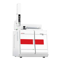
Endress+Hauser Analytik Jena multi N/C 2100S Operating Manual (112 pages)
TOC/TNb Analyzers
Brand:
Endress+Hauser
| Category:
Measuring Instruments
| Size: 9.55 MB
Table of Contents
Table of Contents
3
1 Basic Information
7
User Manual Notes
7
Area of Application
8
General
8
Analyzer Area of Application
8
Intended Use
9
Warranty and Liability
9
2 Safety Instructions
11
Safety Markings on the Analyzer
11
Technical Condition
11
Requirements for the Operating Personnel
12
Safety Instructions, Transport and Installation
13
Safety Instructions - Operation
13
General
13
Safety Instructions - Protection against Explosion and Fire
14
Safety Instructions - Electrical Equipment
14
Safety Instructions for Compressed Gas Containers and Systems
14
Handling of Auxiliary and Operating Materials
15
Safety Instructions - Service and Repair
16
Behavior During Emergencies
16
3 Function and Setup
17
System Design
17
Fig. 1 Front View (Doors Open)
17
Components for Sample Preparation
18
Fig. 2 Lateral View Left (Side Wall Removed)
18
Fig. 3 Locks at the Top of the Device
18
Pneumatics/Hose System
19
Fig. 4 Toggle Switch for the Manual Operation of the Septum-Free TC Lock
19
Fig. 5 Hose Diagram
20
Fig. 6 Needle Valve to Adjust the NPOC Purging Flow (See Arrow)
21
Fig. 7 Condensate Pump
22
Fig. 8 Phosphoric Acid Pump
22
Combustion System
23
Fig. 9 Different Fast Connector Designs
23
Fig. 10 Fingertight Screw Connection
23
Components for Measuring Gas Drying and Cleaning
24
Fig. 11 Combustion Furnace (See Arrow)
24
Fig. 12 Condensation Coil and TIC Condensation Module
25
Fig. 13 Water Traps
25
Detectors
26
Fig. 14 Halogen Trap
26
Indicator and Control Elements, Connectors
28
Fig. 15 LED to Indicate Readiness for Operation
28
Fig. 16 LED Strip (Right Door Open)
28
Accessories
29
Fig. 17 Connections on the Rear of the Device
29
Extension Options for the Analyzer
30
Principle of Operation
31
Fig. 18 Principle of Operation
31
Measuring Method
32
TC Analysis
32
TOC Analysis
32
TIC Analysis
33
NPOC Analysis
33
NPOC Analysis According to the NPOC Plus Method
33
TN B -Analysis
34
Catalysts
34
Calibration
34
Calibration Strategies
34
Day Factor
35
Calibration Method in Multiwin
35
Method Characteristics
37
Other Calculations
38
Blank Values
38
Blank Water Values
38
Boat Blank Value
40
4 First Commissioning
41
Site Requirements
41
Installation Conditions
41
Space Requirement
41
Energy Supply
42
Gas Supply
42
Unpacking and Placing the Analyzer
42
5 Connecting Add-On Devices
43
Autosampler as 60
43
Fig. 19 as 60 Mounted on the Analyzer Multi N/C 2100S
43
Chemiluminescence Detector (CLD)
45
Fig. 20 CLD - Display Elements, Mains Connection and Media Connections
45
External Solids Module HT 1300 (Not for Multi N/C 2100S Pharma)
47
Fig. 21 Media Connections on the Backplate of the Solids Module
47
6 Operation
48
General Information for the Analysis Work
48
Switching on the Analyzer (Standard Commissioning)
48
Carrying out the Calibration
50
Preparing and Starting the Calibration
50
Fig. 22 Window CALIBRATION - DATA of NEW CALIBRATION
51
Displaying Calibration Results
53
Fig. 23 Window CURRENT SAMPLE DATA (with Sampler Operation)
53
Fig. 24 Window CALIBRATION - DATA of NEW CALIBRATION
54
Editing an Existing Calibration
55
Fig. 25 Disabling Individual Measured Values of a Calibration
55
Linking Calibration Parameters to a Method
56
Fig. 26 Window Link to Method
57
Managing Calibration Data
58
Fig. 27 Window LINK with METHOD with Three Areas
58
Fig. 28 Window SELECTION CALIBRATION Report
59
Performing Measurements
60
Measurement with Manual Sample Supply
60
Measurement with Sampler
61
7 Maintenance and Care
63
Maintenance Intervals
63
Adjustment and Setup Tasks
65
Adjust Autosampler
65
Fig. 29 Adjusting the Syringe Piston
67
Adjust the NPOC Purging Flow (Not for Multi N/C 2100S Pharma)
68
Replacing the Water Traps
69
Fig. 30 Water Traps at the Gasbox, Left Side Panel Opened
71
Replacing the Halogen Trap
72
Fig. 31 Halogen Trap
72
Exchanging the Catalyst
73
Lifetime of the Catalyst
73
Removing the Combustion Tube
73
Filling the Combustion Tube
75
Inserting the Combustion Tube
76
Regenerating the TIC Reactor
78
Maintaining the TIC Condensate Container and Condensation Coil
79
Removing and Cleaning the TIC Condensate Container and Condensation Coil
79
Installing the TIC Condensate Container and Condensation Coil
81
Removing and Installing the Combustion Furnace
83
Removing the Combustion Furnace
83
Installing the Combustion Furnace
84
Removing and Replacing the Pump Hose
85
7.10 Replacing the Hose Connections
88
7.11 Checking the System for Tightness
89
Fig. 32 Angled FAST Connector with Connected Hose
89
Fig. 33 Replacing the Fingertight Connection
89
7.12 Replacing the Septa
90
Fig. 34 TIC Sluice with Septum Seal
90
8 Fault Removal
91
General Information
91
Error Messages in Multiwin
92
Status Errors - Indications in the Window System State
96
Equipment Faults and Analytical Problems
98
9 Transport and Storage
103
Transport
103
Preparing the Analyzer for Transport
103
Transport Notes
104
Moving the Analyzer in the Laboratory
104
Storage
105
Recommissioning after Transport or Storage
105
Assembling the Analyzer after Transport or Storage
105
Connecting the Analyzer
106
Fig. 35 Mains Connection and Gas Connections at the Multi N/C 2100S
106
10 Disposal
109
10.1 Waste Water
109
10.2 Halogen Trap
109
10.3 Catalyst
109
10.4 Analyzer
109
11 Specifications
110
11.1 Technical Data
110
11.2 Standards and Directives
112
Advertisement
Endress+Hauser Analytik Jena multi N/C 2100S Operating Manual (113 pages)
TOC/TNb Analyzers
Brand:
Endress+Hauser
| Category:
Measuring Instruments
| Size: 18.27 MB
Table of Contents
Table of Contents
3
About this User Manual
7
Basic Information
7
Analyzer Area of Application
8
Intended Use
8
Security
10
Safety Labeling on the Device
10
Requirements for the Operating Personnel
11
Safety Instructions, Transport and Commissioning
11
Safety Instructions - Protection against Explosion and Fire
12
Safety Instructions: During Operation
12
Summary of Safety Instructions
12
Electrical System Safety Instructions
13
Safety Instructions for the Operation of Compressed Gas Containers and Compressed Gas Systems
13
Handling of Auxiliary and Operating Materials
13
Safety Instructions - Maintenance and Repair
14
Behavior During Emergencies
15
Figure 1 Analyzer, Front Doors Opened
16
Layout
16
Function and Design
16
Figure 2 Analyzer, Left Side Wall Opened
17
Figure 3 Sample Supply System (on Device Top)
17
Sample Supply System
17
Hose System
18
Figure 4 Toggle Switch for Manual Operation of the TC Lock
18
Figure 5 Hose Diagram
18
Figure 6 Setting the NPOC Purge Flow
19
Figure 7 Condensate Pump
19
Figure 10 Fingertight Screw Connection
20
Figure 8 Phosphoric Acid Pump
20
Figure 9 FAST Connector
20
Combustion System
21
Measuring Gas Drying and Cleaning
21
Figure 11 Combustion Furnace
21
Figure 12 Condensation Coil and TIC Condensation Module
22
Figure 13 Water Traps
23
Figure 14 Halogen Trap
23
Detection
24
Indicator and Control Elements, Connections
25
Figure 15 Status LED
25
Figure 16 LED Strip (Right Door Open)
25
Figure 17 Device Rear
26
Accessories
27
Additional Options for the Analyzer
27
Function and Measuring Principle
28
Figure 18 Principle of Operation
28
TIC Analysis
29
TC Analysis
29
TOC Analysis
29
Measuring Methods
29
NPOC Analysis
30
DOC Analysis
30
TN Analysis
30
Catalysts
31
Calibration
31
Calibration Strategies
31
Daily Factor
32
Calibration Method
32
Method Characteristics
33
Other Calculations
34
Blank Values
34
Water Blank Values
34
Eluate Blank Value
35
Boat Blank Value
36
Device Layout and Space Requirements
37
Installation Conditions
37
Ambient Conditions
37
Installation and Commissioning
37
Power Supply
38
Gas Supply
38
Figure 19 Space Required for Multi N/C 2100S with Modules
38
Unpacking and Setting up the Device
39
Installing and Commissioning the Analyzer
39
Figure 20 Device Rear
40
Connecting Accessories
42
AS 60 Autosampler
42
Figure 21 Fasten the Autosampler on the Analyzer
43
Figure 22 Inserting the Syringe
43
Chemiluminescence Detector (CLD)
45
Figure 23 Chemiluminescence Detector (CLD)
45
External Solids Module
47
Figure 24 Connections on the Backplate of the Solids Module
47
Integrated Solids Module
48
Figure 25 Layout of the Integrated Solids Module
48
Operation
52
General Notes
52
Switching on the Analyzer
53
Switching off the Analyzer
54
Carrying out Calibration
54
Preparing and Starting Calibration
54
Figure 26 Data for New Calibration
55
Displaying the Calibration Results
56
Figure 27 Current Sample Data
56
Figure 28 Performed Calibration Data
57
Editing Calibration
58
Linking a Calibration to a Method
58
Figure 29 Linking a Calibration to a Method (3 Calibration Ranges)
59
Managing Calibration Data
60
Performing Measurements
60
Measurement with Manual Sample Feed
60
Measurement with Autosampler
62
Operating the Integrated Solids Module
63
Figure 30 Inserting the Sample Boat in the Solids Module
64
Maintenance and Care
65
Maintenance Overview
65
Adjustment and Setting
66
Adjusting the Autosampler
66
Figure 31 Selecting the Adjustment Position
67
Setting the NPOC Purge Flow
68
Figure 32 Grounding Conductor Connection on the Side Wall
69
Figure 33 Setting the Purge Flow
69
Maintenance for Lock Septums
70
Figure 34 Setting the NPOC Purge Flow
70
Replacing the Pump Hose
71
Figure 35 Septum on the TIC Lock
71
Replacing the Hose Connections
73
Checking the System for Leaks
74
Figure 36 FAST Connector, Angled
74
Figure 37 Replacing the Fingertight Connection
74
Replacing the Catalyst
75
Removing the Combustion Tube
75
Filling the Combustion Tube
76
Installing the Combustion Tube
78
Removing and Installing the Combustion Furnace
80
Removing the Combustion Furnace
80
Installing the Combustion Furnace
81
Cleaning the TIC Condensate Container and Condensation Coil
82
6.10 Replacing the Water Traps
86
Figure 38 Replacing the Water Traps on the Front Side
87
Figure 39 Replacing the Water Traps on the Gas Box
88
6.11 Replacing the Halogen Trap
89
Figure 40 Replacing the Halogen Trap
90
6.12 Removing the Integrated Solids Module
91
Maintaining the Chemiluminescence Detector (CLD)
92
Troubleshooting
93
Software Error Messages
93
Status Errors
97
Device Errors
99
Disposal
104
Preparing the Analyzer for Transport
105
Transport and Storage
105
Transport
105
Moving the Device in the Laboratory
106
Storage
107
Specifications
108
10.1 Technical Data
108
10.2 Standards and Directives
109
Revision Overview
111
Table of Figures
112
Advertisement
Related Products
Endress+Hauser Analytik Jena multi N/C 2100S duo
Endress+Hauser Proservo NMS5
Endress+Hauser Nanomass Gas Density
Endress+Hauser Prothermo NMT532
Endress+Hauser Proservo NMS80
Endress+Hauser Proservo NMS83
Endress+Hauser Nivotester FTL325N
Endress+Hauser Tankvision Multi Scan NXA83
Endress+Hauser NRF81
Endress+Hauser Analytik Jena Multi X 2500
Endress+Hauser Categories
Measuring Instruments
Transmitter
Radar
Switch
Accessories
More Endress+Hauser Manuals
Login
Sign In
OR
Sign in with Facebook
Sign in with Google
Upload manual
Upload from disk
Upload from URL