Sign In
Upload
Manuals
Brands
Endress+Hauser Manuals
Measuring Instruments
multi N/C 2300
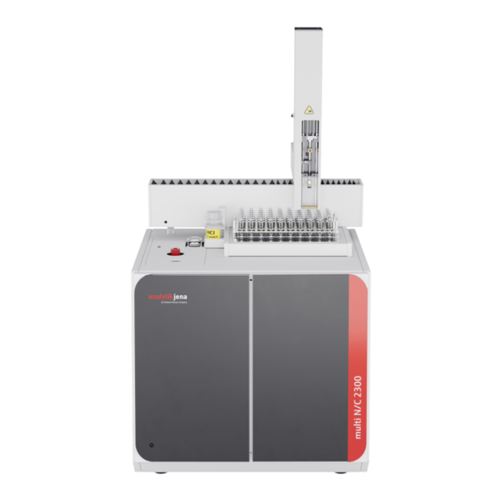
Endress+Hauser multi N/C 2300 Manuals
Manuals and User Guides for Endress+Hauser multi N/C 2300. We have
1
Endress+Hauser multi N/C 2300 manual available for free PDF download: Operating Manual
Endress+Hauser multi N/C 2300 Operating Manual (107 pages)
TOC/TNb Analyzers
Brand:
Endress+Hauser
| Category:
Measuring Instruments
| Size: 12 MB
Table of Contents
Table of Contents
3
Basic Information
7
About this User Manual
7
Analyzer Area of Application
8
Intended Use
8
Safety
10
Safety Labeling on the Device
10
Requirements for the Operating Personnel
11
Safety Instructions, Transport and Commissioning
11
Summary of Safety Instructions
12
Safety Instructions - Protection against Explosion and Fire
12
Safety Instructions: During Operation
12
Electrical System Safety Instructions
13
Safety Instructions for the Operation of Compressed Gas Containers and Compressed Gas Systems
13
Handling of Auxiliary and Operating Materials
13
Safety Instructions - Maintenance and Repair
14
Behavior During Emergencies
15
Fig. 1 Analyzer, Front Doors Opened
16
Function and Design
16
Layout
16
Fig. 2 Analyzer, Left Side Wall Opened
17
Fig. 3 Sample Supply System (on Device Top)
17
Sample Supply System
18
Fig. 4 Toggle Switch for Manual Operation of the TC Lock
18
Hose System
19
Fig. 5 Hose Diagram
19
Fig. 6 Setting the NPOC Purge Flow
19
Fig. 7 Condensate Pump
20
Fig. 8 Phosphoric Acid Pump
20
Fig. 9 FAST Connector
20
Combustion System
21
Measuring Gas Drying and Cleaning
21
Fig. 10 Fingertight Screw Connection
21
Fig. 11 Combustion Furnace
21
Fig. 12 Condensation Coil and TIC Condensation Module
22
Fig. 13 Water Traps
23
Fig. 14 Halogen Trap
23
Detection
24
Indicator and Control Elements, Connections
25
Fig. 15 Status LED
25
Fig. 16 LED Strip (Right Front Door Open)
25
Accessories
26
Fig. 17 Device Rear
26
Additional Options for the Analyzer
27
Function and Measuring Principle
27
Fig. 18 Principle of Operation
28
Measuring Methods
29
TC Analysis
29
TOC Analysis
29
TIC Analysis
29
NPOC Analysis
29
Additional Sum Parameters
30
TN Analysis
30
DOC Analysis
30
Catalysts
31
Calibration
31
Calibration Strategies
31
Daily Factor
32
Calibration Method
32
Method Characteristics
34
Other Calculations
34
Blank Values
34
Water Blank Values
34
Eluate Blank Value
36
Boat Blank Value
36
Installation and Commissioning
37
Installation Conditions
37
Ambient Conditions
37
Device Layout and Space Requirements
37
Fig. 20 Space Required for Multi N/C 2300 Duo Modular Measuring System
38
Fig. 19 Space Required for Multi N/C 2300 with Modules
38
Power Supply
39
Gas Supply
39
Unpacking and Setting up the Device
39
Installing and Commissioning the Analyzer
39
Fig. 21 Device Rear
41
Connecting Accessories
43
AS 60 Autosampler
43
Fig. 22 Fasten the Autosampler on the Analyzer
44
Fig. 23 Inserting the Syringe
45
Chemiluminescence Detector (CLD)
46
Fig. 24 Chemiluminescence Detector (CLD)
46
External Solids Module
47
Integrated Solids Module
48
Fig. 25 Connections on the Backplate of the Solids Module
48
Fig. 26 Layout of the Integrated Solids Module
49
General Notes
53
Operation
53
Switching on the Analyzer
54
Switching off the Analyzer
55
Performing Measurements
56
Manual Sample Feed at the Locks
56
Create Sequence and Measure with Manual Sample Feed
56
Creating a Sequence and Measuring with Automatic Sample Feed
58
Operating the Integrated Solids Module
60
Fig. 27 Inserting the Sample Boat in the Solids Module
61
Maintenance and Care
62
Maintenance Overview
62
Adjustment and Setting
63
Adjusting the Autosampler
63
Setting the NPOC Purge Flow
65
Fig. 28 Grounding Conductor Connection on the Side Wall
65
Maintenance for Lock Septums
66
Fig. 29 Setting the NPOC Purge Flow
66
Fig. 30 Septum on the TIC Lock
67
Replacing the Pump Hose
67
Replacing the Hose Connections
69
Fig. 31 FAST Connector, Angled
70
Checking the System for Leaks
71
Replacing the Catalyst
71
Fig. 32 Replacing the Fingertight Connection
71
Removing the Combustion Tube
72
Filling the Combustion Tube
73
Installing the Combustion Tube
75
Removing and Installing the Combustion Furnace
77
Removing the Combustion Furnace
77
Installing the Combustion Furnace
78
Cleaning the TIC Condensate Container and Condensation Coil
79
6.10 Replacing the Water Traps
83
Fig. 33 Replacing the Water Traps on the Front Side
83
Fig. 34 Replacing the Water Traps on the Gas Box
84
Fig. 35 Replacing the Halogen Trap
85
6.11 Replacing the Halogen Trap
85
6.12 Removing the Integrated Solids Module
86
Maintaining the Chemiluminescence Detector (CLD)
87
Fig. 36 Replacing the Adsorber Cartridge
88
Troubleshooting
89
Software Error Messages
89
Status Errors
93
Device Errors
94
Preparing the Analyzer for Transport
99
Transport
99
Transport and Storage
99
Moving the Device in the Laboratory
100
Storage
101
Disposal
102
Specifications
103
10.1 Technical Data of the Basic Device
103
10.2 Technical Data of the Accessories
105
10.3 Standards and Directives
105
List of Figures
107
Advertisement
Advertisement
Related Products
Endress+Hauser Analytik Jena multi N/C 2100S
Endress+Hauser Analytik Jena multi N/C 2100S duo
Endress+Hauser multi N/C 2300 duo
Endress+Hauser multi N/C 2300 N
Endress+Hauser Proservo NMS 7 series
Endress+Hauser Prothermo NMT 538
Endress+Hauser Prothermo NMT 539
Endress+Hauser Proservo NMS81
Endress+Hauser Prothermo NMT532
Endress+Hauser Proservo NMS83
Endress+Hauser Categories
Measuring Instruments
Transmitter
Radar
Switch
Accessories
More Endress+Hauser Manuals
Login
Sign In
OR
Sign in with Facebook
Sign in with Google
Upload manual
Upload from disk
Upload from URL