Sign In
Upload
Manuals
Brands
Eaton Manuals
UPS
93PR-20kVA
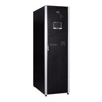
Eaton 93PR-20kVA Backup Power UPS Manuals
Manuals and User Guides for Eaton 93PR-20kVA Backup Power UPS. We have
1
Eaton 93PR-20kVA Backup Power UPS manual available for free PDF download: Installation And Operation Manual
Eaton 93PR-20kVA Installation And Operation Manual (122 pages)
Brand:
Eaton
| Category:
UPS
| Size: 8.73 MB
Table of Contents
Table of Contents
27
Chapter 1 SAFETY INSTRUCTIONS TIONS
33
Certification
35
User Precautions
35
Conventions Used in this Manual
36
Table 1-1: Acronyms and Abbreviations
37
Environment
38
Getting Help
38
Chapter 2 INTRODUCTION
39
Figure 2-1: Eaton 93PR UPS
39
Figure 2-2: Structure of 15-40K Product
40
Figure 2-3: Structure of 60-80K Product
41
Internal Structure of UPS System
42
Figure 2-4: 93PR UPS Wiring Diagram
42
Operation Modes of the UPS
43
AC Power Online Operation Mode
43
Figure 2-5: Route of the Electric Energy Running through the UPS in Online Mode
44
Figure 2-6: Route of the Electric Energy Running through the UPS in ESS Mode
45
Battery Mode
46
Figure 2-7: Route of the Electric Energy Running through the UPS in Battery Mode
46
Bypass Mode
47
Figure 2-8: Route of the Electric Energy Running through the UPS in Bypass Mode
47
Features of the UPS
48
Advanced Battery Management(ABM)
48
Eaton Hotsync Wireless Parallel Technology (Hotsync)
48
Software and Communication Features
48
User Interface
48
Power Supply Management Software
49
Battery System
49
Basic System Configuration
49
Table 2-1: Standards and Optional UPS Accessories
49
Chapter 3 UPS INSTALLATION PLAN
50
Creating an Installation Plan
50
Site Preparations
51
Environmental and Installation Precautions
51
Table 3-1: Dimensions and Weights
52
Figure 3-1: Clearance for the UPS Cabinet
53
Table 3-2: Space Reservation for the UPS Cabinet
53
Figure 3-2: UPS Dimensions (15-40K)
54
Figure 3-3: UPS Dimensions (60-80K)
55
Power Supply and Wiring Preparation of the UPS System
56
Table 3-4: Requirements on 15-20K Connecting Terminals and Torque
58
Table 3-5: Requirements on 30-40K Connecting Terminals and Torques
59
Table 3-6: Requirements on 60-80K Connecting Terminals and Torques
60
Preparation for UPS Interface Wiring
61
Chapter 4 UPS SYSTEM INSTALLATION
62
Preliminary Installation Information
62
UPS Cabinet Inspection and Unpacking
62
Figure 4-1: 15-40K Unpacking Diagram
64
Figure 4-2: 60-80K Unpacking Diagram
65
System Installation
66
Mechanical Installation
66
Cable Installation
66
Figure 4-3: Gland Plate and Connector Locations
67
Figure 4-4: Locations of Cover Plate and Connecting Terminals (60-80K)
68
Installation of External Battery Cabinet
69
Supported Battery Configurations
70
Wiring of the UPS Parallel System
70
Overview of Power Cables
70
Control Signal Overview
72
Figure 4-5: Schematic Diagram of the Parallel UPS System
72
Installation of the Parallel Control Wiring
73
Figure 4-6: Simplified Wiring of CAN and Pull-Chain of the Parallel UPS System
73
Chapter 5 COMMUNICATION INTERFACES
74
Figure 5-1: Communication Interfaces
74
Mini-Slots
76
Figure 5-2: Gigabit Network Card
76
Figure 5-3: Second-Generation Environmental Monitoring Probe
76
Figure 5-4: Industrial Gateway Card
77
Figure 5-5: Standard AS400/RS232 Card
77
Intelligent Power Manager (IPM) Software
78
Signal Input Monitoring
78
Chapter 6 UPS OPERATING INSTRUCTIONS
79
UPS Control Panel and Indicator Lamps
79
Control Panel
79
Figure 6-1: UPS Controls and Indicators
80
Use of LCD Control Panel
81
Status Indicator Lamps
81
System Logs
81
Table 6-1: Status Indicator Lamps
81
Use of Touch Screen
82
Use Menu
82
Figure 6-2: Components of the Touch Screen (Home Interface)
82
Meters
83
Figure 6-3: Menu Interface
83
Table 6-2: Options Displayed on the Menu
83
Table 6-3: Menu of Meters Functions
83
Figure 6-4: Input Interface
84
Figure 6-5: Output Interface
84
Figure 6-6: Bypass Interface
84
System Control Instructions
85
Figure 6-7: Battery Interface
85
Figure 6-8: Password Verification Interface
85
Table 6-4: Structure of Control Menu
85
Figure 6-9: System Interface
86
Figure 6-10: Switch to Bypass Interface
86
Figure 6-11: Confirmation Interface
87
Figure 6-12: UPS Interface
87
Use of Log Menu
88
Figure 6-13: UPM Interface
88
Figure 6-14: UPM Shutdown Interface
88
Table 6-5: Structure of Log Menu
88
Figure 6-15: Active Log Interface
89
Figure 6-16: History Log Interface
89
Figure 6-17: Clear Log Interface
89
Use of Info. Menu
90
Use of Setting Menu
90
Figure 6-18: Info. Interface 1
90
Figure 6-19: Info. Interface 2
90
Figure 6-20: Password Verification Setting Interface
91
Figure 6-21: Setting Interface
91
Table 6-6: Structure of Setting Menu
91
Figure 6-22: Setting - General Interface
92
Figure 6-23: Setting - General - Time Interface
92
Figure 6-24: Setting - Output Interface
93
Figure 6-25: Setting - Meters Interface
93
Figure 6-26: Setting - Password Interface
93
Figure 6-27: Control Password Modification Interface
94
Figure 6-28: Control Password Modification Interface
94
Figure 6-29: Control Password Modification Interface
95
Figure 6-30: Control Password Modification Interface
95
Use of Service Reminder Function
96
Figure 6-31: Setting Password Modification Interface
96
Figure 6-32: Service Maintenance Reminder Interface
96
Figure 6-33: Service Maintenance Reminder Setting Interface
97
Figure 6-34: Location of Service Reminder Function
97
Figure 6-35: Service Reminder Settings Page
98
Figure 6-36: Fan Replacement Reminder Settings
98
System Operation
99
Start the UPS in "Online" Mode (Default Mode)
99
Start the UPS in "Bypass" Mode
99
Switch from "Online" Mode to "Bypass" Mode
100
Switch from "Bypass" Mode to "Online" Mode
100
Switch from "Online" Mode to "ESS" Mode
101
Switch from "ESS" Mode to "Online" Mode
101
System Shutdown
101
Single-UPS Operation
102
Single-UPS Startup
102
UPS Shutdown
103
Use of Remote Emergency Power off (REPO) Switch
104
Transfer the UPS from Double Conversion Mode to Maintenance Bypass Mode
105
Figure 6-37: Switch Status in Online Mode
105
Figure 6-38: Switch Status in Maintenance Bypass Mode
105
Switch from "Maintenance Bypass" Mode to "Online" Mode
106
Figure 6-39: Switch Status in Maintenance Bypass Mode
106
Figure 6-40: Switch Status in Online Mode
106
Chapter 7 UPS MAINTENANCE
107
Important Safety Instructions
107
Carry out Preventive Maintenance
108
Daily Maintenance
108
Monthly Maintenance
108
Figure 7-1: Location of 15-40K Air Filter Screen
109
Figure 7-2: Location of 60-80K Air Filter Screen
109
Regular Maintenance
110
Annual Maintenance
110
Battery Maintenance
110
Installation of Battery
110
Maintenance Training
111
Chapter 8 Technical Indicators of Product
112
Models
112
Technical Indicators
112
Standard
112
UPS Input
113
UPS Output
113
Battery Specifications
114
Environment
114
Table 8-2: Requirements on the Environment for Transportation and Storage Within 1 Year
115
Chapter 9 WARRANTY
116
Chapter 10 INSTALLATION CHECKLIST
117
Table 10-1: User Settings
119
Table 10-2: Configuration Settings
119
Advertisement
Advertisement
Related Products
Eaton 93PR 25(75)
Eaton 93PR Series
Eaton 93PR 50(75)
Eaton 93PR 75(75)
Eaton 93PR-300
Eaton 93PR-1200
Eaton 93PR-15kVA
Eaton 93PR-30kVA
Eaton 93PR-40kVA
Eaton 93PR-60kVA
Eaton Categories
UPS
Circuit breakers
Industrial Equipment
Switch
Industrial Electrical
More Eaton Manuals
Login
Sign In
OR
Sign in with Facebook
Sign in with Google
Upload manual
Upload from disk
Upload from URL