Sign In
Upload
Manuals
Brands
Delta Manuals
DC Drives
VFD220B2343A
Delta VFD220B2343A Manuals
Manuals and User Guides for Delta VFD220B2343A. We have
1
Delta VFD220B2343A manual available for free PDF download: User Manual
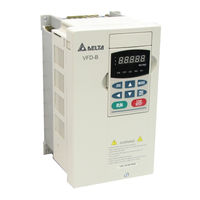
Delta VFD220B2343A User Manual (179 pages)
High Performance/User-Friendly Powerful AC Motor Drives
Brand:
Delta
| Category:
DC Drives
| Size: 4.46 MB
Table of Contents
Getting Started
4
Warning
4
Table of Contents
6
Nameplate Information
9
Example for 1Hp/0.75Kw 3-Phase 230V AC Drive
9
Model Explanation
9
Chapter 1 Receiving and Inspections
9
Series Number Explanation
10
Storage and Installation
11
Ambient Conditions
11
Chapter 2 Storage and Installation
11
Installation
12
Short Circuit Withstand
13
General Wiring Information
13
Applicable Codes
13
Chapter 3 Wiring
13
Basic Wiring Diagram
14
Terminal Explanation
14
Wiring for SINK Mode and SOURCE Mode
17
Sink Mode
17
Source Mode
17
External Wiring
18
Power Supply
18
EMI Filter
18
Terminal Explanations
19
Control Terminals Explanations
19
Main Circuit Wiring
21
Control Terminal
21
Power Terminal
21
3HP to 5HP (VFD022B21A, VFD037B23A, VFD037B43A)
22
40 HP to 60 HP 460V (VFD300B43A, VFD370B43A, VFD450B43A)
26
75-100 Hp 460V (Vfd550B43A, Vfd750B43A)
27
Wiring Notes
28
Motor Operation Precautions
29
VFD-PU01 Dimensions
31
Chapter 4 Digital Keypad Operation
31
Description of the Digital Keypad VFD-PU01
32
Operation Steps of the Digital Keypad VFD-PU01
34
Selecting Mode
34
Setting Parameters
34
To Shift Data
34
Parameter Reset
35
Identity Code of AC Drive
35
Chapter 5 Description of Parameter Settings
35
Group 0: User Parameters
35
Start-Up Display Page Selection
36
Content of Multi Function Display
36
User Defined Coefficient K
36
Software Version
37
Password Decode
37
Password Input
37
Password Decode Flow Chart
38
Control Methods
38
Reserved
38
Group 1: Basic Parameters
39
Maximum Output Frequency (Fmax)
39
Maximum Voltage Frequency (Fbase)
39
Maximum Output Voltage (Vmax)
39
Minimum Output Frequency (Fmin)
40
Minimum Output Voltage (Vmin)
40
Upper Bound of Output Frequency
40
V/F Curve
40
Lower Bound of Output Frequency
41
Acceleration Time 1 (Taccel 1)
41
Deceleration Time 1 (Tdecel 1)
41
Jog Acceleration Time
42
Jog Deceleration Time
42
Jog Frequency
42
Accel/Decel Time Definition
42
Auto-Acceleration / Deceleration
43
Acceleration S-Curve
43
Deceleration S-Curve
43
Unit for Accel/Decel Time
44
Group 2: Operation Method Parameters
45
Source of First Frequency Command
45
Source of Second Frequency Command
45
Source of First Operation Command
46
Source of Second Operation Command
46
Stop Method
46
PWM Carrier Frequency Selections
47
Motor Direction Control
48
2-Wire/ 3-Wire Operation Control Modes
48
Line Start Lockout
48
Loss of ACI Signal (4-20Ma)
49
Up/Down Key Mode
49
Source of the Master Frequency Command (FCHA)
49
Source of the Auxiliary Frequency Command (FCHB)
50
Combination of the Master and Auxiliary Frequency Command
50
Keyboard Frequency Command
50
Group 3: Output Function Parameters
51
Multi-Function Output Terminal
51
Multi-Function Output Terminal MO1
51
Multi-Function Output Terminal MO2
51
Desired Frequency Attained 2
53
Analog Output Signal (AFM)
53
Analog Output Gain
53
Digital Output Multiplying Factor
54
Terminal Count Value
54
Preliminary Count Value
54
EF Active When Preliminary Count Value Attained
55
Fan Control
55
Group 4: Input Function Parameters
56
AVI Analog Input Bias
56
AVI Bias Polarity
56
AVI Input Gain
56
AUI Input Gain
57
No AUI Negative Bias Command
57
Max. Output Freq.
60
Multi-Function Input Terminal (MI1)
60
Multi-Function Input Terminal (MI2)
60
Multi-Function Input Terminal (MI3)
60
Digital Terminal Input Debouncing Time
64
AVI Analog Input Delay
64
ACI Analog Input Delay
64
AUI Analog Input Delay
64
Gear Ratio for Simple Index Function
65
Index Angle for Simple Index Function
65
Deceleration Time for Simple Index Function
65
Group 5: Multi-Step Speed and PLC (Process Logic Control) Parameters
66
PLC Mode
66
1St Step Speed Frequency
66
2Nd Step Speed Frequency
66
Continuously Executes Program Cycles
67
Execute One Cycle Step by Step
68
PLC Operation Execution One Cycle Step by Step
68
PLC Forward/Reverse Motion
68
Time Unit Settings
70
Skip Frequency Width
70
Bias Frequency Width
70
Group 6: Protection Parameters
72
Over-Voltage Stall Prevention
72
Over-Current Stall Prevention During Acceleration
72
Over-Current Stall Prevention During Operation
73
Over-Torque Detection Mode (OL2)
74
Over-Torque Detection Level
74
Over-Torque Detection Time
74
Electronic Thermal Overload Relay Selection
74
Present Fault Record
75
Second most Recent Fault Record
75
Third most Recent Fault Record
75
Fourth Recent Fault Record
75
Low-Current Detection Level
76
Low-Current Detection Time
76
Low-Current Treatment
76
Low-Current Detection Restart Delay Time
76
User-Defined Low-Voltage Detection Level
77
User-Defined Low-Voltage Detection Time
77
Group 7: Motor Parameters
78
Motor Rated Current
78
Motor No-Load Current
78
Torque Compensation
78
Motor Line-To-Line Resistance R1
79
Motor Rated Slip
79
Slip Compensation Limit
80
Torque Compensation Time Constant
80
Slip Compensation Time Constant
80
Accumulative Motor Operation Time (Min.)
80
Group 8: Special Parameters
81
DC Braking Current Level
81
DC Braking Time During Start-Up
81
DC Braking Time During Stopping
81
Momentary Power Loss Operation Selection
82
Maximum Allowable Power Loss Time
82
Baseblock Time for Speed Search (BB)
82
Current Limit for Speed Search
82
Skip Frequency 1 Upper Bound
83
Skip Frequency 1 Lower Bound
83
Auto Restart after Fault
83
Automatic Energy-Saving
83
Automatic Voltage Regulation (AVR)
84
Software Setting of the Braking Level
84
Base Block Speed Search
85
Speed Search During Start-Up
86
Speed Search Frequency During Start-Up
86
Auto Reset Time at Restart after Fault
87
Compensation Coefficient for Motor Instability
87
Group 9: Communication Parameters
88
Communication Address
88
Transmission Speed
88
Transmission Fault Treatment
88
11-Bit Character Frame (for RTU)
90
Communication Protocol
90
Communication Data Frame
90
ASCII Mode
90
Adr
91
CMD (Command Code) and DATA (Data Characters)
91
Command Message
91
Response Message
91
CHK (Check Sum)
95
Exception Response
99
Communication Program of PC
100
HMI Register 1
101
HMI Register 2
101
Response Delay Time
101
Group 10: PID Controls
102
Input Terminal for PID Feedback
102
Gain over the PID Detection Value
102
Proportional Gain (P)
102
Derivative Control (D)
103
Upper Bound for Integral Control
103
Primary Delay Filter Time
103
PID Output Frequency Limit
103
Feedback Signal Detection Time
104
Deviation Range of PID Feedback Signal Error
104
Treatment of the Erroneous Feedback Signals
104
PG Pulse Range
104
Proportional Speed Control (P)
105
Integral Speed Control (I)
105
Speed Control Output Frequency Limit
105
Sample Time for Refreshing the Content of 210DH and 210EH
105
PID Control Block Diagram
106
Speed Control Diagram
106
Group 11: Fan and Pump Control Parameters
107
V / F Curve Selection
107
Start-Up Frequency of the Auxiliary Motor
107
Stop Frequency of the Auxiliary Motor
107
Sleep/Wake up Detection Time
108
Sleep Frequency
108
Wakeup Frequency
109
Periodic Inspection
111
Periodic Maintenance
111
Chapter 6 Maintenance and Inspections
111
Common Problems and Solutions
113
Chapter 7 Troubleshooting and Fault Information
113
Emergency Stop
116
Ground Fault
116
Group 0: User Parameters
119
Chapter 8 Summary of Parameter Settings
119
Group 1 Basic Parameters
121
Group 3 Output Function Parameters
125
Group 4 Input Function Parameters
127
Group 5 Multi-Step Speed and PLC Parameters
129
Group 6 Protection Parameters
131
Group 7 Motor Parameters
133
Group 10: PID Control Parameters
137
Appendix A Specifications
139
Electrical Characteristics
141
Input Frequency
141
Output Voltage
141
Output Frequency
141
Accessories
143
Non-Fuse Circuit Breaker Chart
143
Fuse Specification Chart
144
All Braking Resistors & Braking Units Use in AC Drives
145
Appendix B Accessories
146
Braking Resistors & Braking Units
146
Amd - Emi Filter Corss Reference
149
Order P/N: RF015B21AA / RF022B43AA
150
Order P/N: RF022B21BA / RF037B43BA
151
Order P/N: RF110B43CA
152
Order P/N: 10TDT1W4C
153
Order P/N: 26TDT1W4C
153
Order P/N: 50TDS4W4C
154
Order P/N: 100TDS84C
154
Order P/N: 200TDDS84C
155
Order P/N: 150TDS84C
155
Order P/N: 180TDS84C
156
Order P/N: 20TDT1W4D
156
Order P/N: 26TDT1W4B4
157
PG Card
158
1 To 2HP (0.75Kw to 1.5Kw)
158
3 To 5HP (2.2Kw to 3.7Kw)
158
7.5HP (5.5Kw) and above
159
Basic Wiring Diagram with RPM Meter Attached
160
PG-02 and Pulse Generator Connections
160
PG-02 Terminal Descriptions
161
Terminals
161
Control Terminals Block Designations
162
Types of Pulse Generators
162
Remote Controller RC-01
163
VFD-B Programming
163
Remote Panel Adapter
164
Remote Panel Adapter for VFDPU01
164
Zero Phase Reactor
165
Appendix C Dimensions
167
VFD007B21A 0.75 Kw (1HP) 230V / 1-Phase
168
VFD015B21A 1.50 Kw (2HP) 230V / 1-Phase
168
VFD015B23A 1.50 Kw (2HP) 230V / 3-Phase
168
VFD015B43A 1.50 Kw (2HP) 460V / 3-Phase
168
VFD015B21B 1.50 Kw (2HP) 230V / 1-Phase
169
VFD015B23B 1.50 Kw (2HP) 230V / 3-Phase
169
VFD022B23B 2.20 Kw (3HP) 230V / 3-Phase
169
VFD022B43B 2.20 Kw (3HP) 460V / 3-Phase
169
2.20 Kw (3HP) 230V / 1-Phase
170
3.70 Kw (5HP) 230V / 3-Phase
170
3.70 Kw (5HP) 460V / 3-Phase
170
VFD055B23A 5.50 Kw (7.50HP) 230V / 3-Phase
171
VFD055B43A 5.50 Kw (7.50HP) 460V / 3-Phase
171
VFD075B23A 7.50 Kw (10.0HP) 230V / 3-Phase
171
VFD075B43A 7.50 Kw (10.0HP) 460V / 3-Phase
171
VFD150B23A 15.0 Kw (20.0HP) 230V / 3-Phase
172
VFD150B43A 15.0 Kw (20.0HP) 460V / 3-Phase
172
VFD185B23A 18.5 Kw (25.0HP) 230V / 3-Phase
172
VFD185B43A 18.5 Kw (25.0HP) 460V / 3-Phase
172
VFD300B23A 30.0 Kw (40HP) 230V / 3-Phase
173
VFD370B23A 37.0 Kw (50HP) 230V / 3-Phase
173
VFD300B43A 30.0 Kw (40HP) 460V / 3-Phase
174
VFD370B43A 37.0 Kw (50HP) 460V / 3-Phase
174
VFD450B43A 45.0 Kw (60HP) 460V / 3-Phase
174
VFD550B43A 55.0 Kw (75HP) 460V / 3-Phase
175
VFD750B43A 75.0 Kw (100HP) 460V / 3-Phase
175
Advertisement
Advertisement
Related Products
Delta VFD220B23A
Delta VFD220B43A
Delta VFD220B53A
Delta VFD220B43W
Delta VFD220B43P
Delta VFD220CP63A-21
Delta VFD220VL23A
Delta VFD220VL43A
Delta VFD220CT43A21C
Delta VFD220A23A
Delta Categories
Plumbing Product
Kitchen & Bath Fixtures
Bathroom Fixtures
Saw
Power Supply
More Delta Manuals
Login
Sign In
OR
Sign in with Facebook
Sign in with Google
Upload manual
Upload from disk
Upload from URL