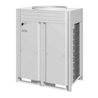
Sign In
Upload
Manuals
Brands
Daikin Manuals
Heat Pump
VRV II RXYQ24MY1K
Daikin VRV II RXYQ24MY1K Manuals
Manuals and User Guides for Daikin VRV II RXYQ24MY1K. We have
1
Daikin VRV II RXYQ24MY1K manual available for free PDF download: Service Manual
Daikin VRV II RXYQ24MY1K Service Manual (310 pages)
R-410A Heat Pump 50/60Hz For High Outdoor Temperature Use
Brand:
Daikin
| Category:
Heat Pump
| Size: 11.5 MB
Table of Contents
Table of Contents
2
Introduction
7
Safety Cautions
7
Preface
11
Part 1 General Information
12
Model Names of Indoor/Outdoor Units
13
External Appearance
14
Indoor Units
14
Outdoor Units
15
Combination of Outdoor Units
16
Capacity Range
17
Part 2 Specifications
18
Outdoor Units
19
Indoor Units
27
Ceiling Suspended Type
41
Part 3 Refrigerant Circuit
54
Refrigerant Circuit
55
Rxyq8M, 10M
55
Functional Parts Layout
57
Rxyq8M, 10M
57
Refrigerant Flow for each Operation Mode
58
Cooling Oil Return Operation
59
Heating Operation
61
Part 4 Function
62
Function General
63
Symbol
63
Operation Mode
64
Basic Control
65
Normal Operation
65
Compressor PI Control
66
Electronic Expansion Valve PI Control
69
Step Control of Outdoor Unit Fans
69
Outdoor Unit Fan Control in Cooling Operation
70
Special Control
71
Startup Control
71
Oil Return Operation
72
Defrosting Operation
74
Pump-Down Residual Operation
75
Standby
76
Stopping Operation
77
Pressure Equalization Prior to Startup
79
Protection Control
80
High Pressure Protection Control
80
Low Pressure Protection Control
81
Discharge Pipe Protection Control
82
Inverter Protection Control
83
STD Compressor Overload Protection
84
Other Control
85
Outdoor Unit Rotation
85
Emergency Operation
86
Demand Operation
88
Heating Operation Prohibition
88
Outline of Control (Indoor Unit)
89
Drain Pump Control
89
Louver Control for Preventing Ceiling Dirt
91
Thermostat Sensor in Remote Controller
92
Thermostat Control While in Normal Operation
94
Thermostat Control in Dry Operation
94
Freeze Prevention
95
Heater Control
96
List of Swing Flap Operations
97
Part 5 Test Operation
98
Test Operation
99
Procedure and Outline
99
Operation When Power Is Turned on
103
Outdoor Unit PC Board Layout
104
Field Setting
105
Field Setting from Remote Controller
105
Detailed Explanation of Setting Modes
110
Field Setting from Outdoor Unit
117
Part 6 Troubleshooting
144
Symptom-Based Troubleshooting
147
Troubleshooting by Remote Controller
150
The INSPECTION / TEST Button
150
Self-Diagnosis by Wired Remote Controller
151
Self-Diagnosis by Wireless Remote Controller
152
Operation of the Remote Controller's Inspection / Test Operation Button
154
Remote Controller Service Mode
155
Remote Controller Self-Diagnosis Function
157
Troubleshooting
160
Troubleshooting by Indication on the Remote Controller
162
A0" Indoor Unit: Error of External Protection Device
162
A1" Indoor Unit: PC Board Defect
163
PC Board Defect
163
A3" Indoor Unit: Malfunction of Drain Level Control System (S1L)
164
A6" Indoor Unit: Fan Motor (M1F) Lock, Overload
166
Fan Motor (M1F) Lock, Overload
166
A7" Indoor Unit: Malfunction of Swing Flap Motor (MA)
167
A9" Indoor Unit: Malfunction of Moving Part of Electronic
169
Malfunction of Moving Part of Electronic Expansion Valve (20E)
169
Expansion Valve (20E)
169
AF" Indoor Unit
171
Drain Level above Limit
171
AF" Indoor Unit: Drain Level above Limit
171
AJ" Indoor Unit: Malfunction of Capacity Determination Device
172
C4" Indoor Unit: Malfunction of Thermistor (R2T) for
173
Malfunction of Thermistor (R2T) for Heat Exchanger
173
Heat Exchanger
173
3.10 " C5 " Indoor Unit
174
Malfunction of Thermistor (R3T) for Gas Pipes
174
C5" Indoor Unit: Malfunction of Thermistor (R3T) for Gas Pipes
174
3.11 " C9 " Indoor Unit
175
C9" Indoor Unit: Malfunction of Thermistor (R1T) for Suction Air
175
CJ" Indoor Unit: Malfunction of Thermostat Sensor in
176
Remote Controller
176
CJ" Indoor Unit: Malfunction of Thermostat Sensor
176
In Remote Controller
176
E1" Outdoor Unit: PC Board Defect
177
PC Board Defect
177
E3" Outdoor Unit: Actuation of High Pressure Switch
178
Actuation of High Pressure Switch
178
E4" Outdoor Unit: Actuation of Low Pressure Sensor
179
Actuation of Low Pressure Sensor
179
E5" Outdoor Unit: Compressor Motor Lock
180
E6" Outdoor Unit: STD Compressor Motor Overcurrent/Lock
181
E7" Outdoor Unit: Malfunction of Outdoor Unit Fan Motor
183
3.19 " E9 " Outdoor Unit
185
Electronic Expansion Valve (Y1E, Y2E)
185
F3" Outdoor Unit: Abnormal Discharge Pipe Temperature
187
F6" Outdoor Unit: Refrigerant Overcharged
188
H7" Outdoor Unit: Abnormal Outdoor Fan Motor Signal
189
3.23 " H9 " Outdoor Unit
190
H9" Outdoor Unit: Malfunction of Thermistor (R1T) for Outdoor Air
190
J2" Outdoor Unit: Current Sensor Malfunction
191
3.25 " J3 " Outdoor Unit
192
J3" Outdoor Unit: Malfunction of Discharge Pipe Thermistor (R3, R31 or 32T)
192
J5" Outdoor Unit: Malfunction of Thermistor (R2T) for
193
Suction Pipe
193
3.27 " J6 " Outdoor Unit
194
Outdoor Unit Heat Exchanger Deicer
194
J7" Outdoor Unit: Malfunction of
195
Receiver Outlet Liquid Pipe Thermistor (R6T)
195
J9" Outdoor Unit: Malfunction of
196
Subcooling Heat Exchanger Gas Pipe Thermistor (R5T)
196
JA" Outdoor Unit: Malfunction of High Pressure Sensor
197
Malfunction of High Pressure Sensor
197
JC" Outdoor Unit: Malfunction of Low Pressure Sensor
198
Malfunction of Low Pressure Sensor
198
3.32 " L4 " Outdoor Unit
199
L4" Outdoor Unit: Malfunction of Inverter Radiating Fin Temperature Rise
199
L5" Outdoor Unit: Inverter Compressor Abnormal
200
Inverter Compressor Abnormal
200
L8" Outdoor Unit: Inverter Current Abnormal
201
Inverter Current Abnormal
201
L9" Outdoor Unit: Inverter Start up Error
202
Inverter Start up Error
202
3.36 " LC " Outdoor Unit
203
Control PC Board
203
LC" Outdoor Unit: Malfunction of Transmission between Inverter and Control PC Board
203
P1" Outdoor Unit: Inverter Over-Ripple Protection
205
Inverter Over-Ripple Protection
205
3.38 " P4 " Outdoor Unit
206
P4" Outdoor Unit: Malfunction of Inverter Radiating Fin Temperature Rise Sensor
206
Electronic Expansion Valve Failure
207
UO" Outdoor Unit: Low Pressure Drop Due to
207
Refrigerant Shortage or Electronic Expansion Valve Failure
207
Reverse Phase, Open Phase
208
U1" Reverse Phase, Open Phase
208
Outdoor Unit: Power Supply Insufficient or Instantaneous Failure
209
Instantaneous Failure
209
U3" Outdoor Unit: Check Operation Not Executed
211
Malfunction of Transmission between Indoor Units
212
U4" Malfunction of Transmission between Indoor Units
212
Remote Controller and Indoor Unit
214
U5" Indoor Unit: Malfunction of Transmission between
214
Indoor Unit: Malfunction of Transmission between Outdoor Units
215
Outdoor Units
215
U8" Indoor Unit: Malfunction of Transmission between
217
Main and Sub Remote Controllers
217
Outdoor Units in the same System
218
U9" Indoor Unit: Malfunction of Transmission between
218
Indoor and Outdoor Units in the same System
218
And Remote Controller
220
UA" Improper Combination of Indoor and Outdoor Units
220
Indoor Unit and Remote Controller
220
UC" Address Duplication of Centralized Controller
221
Malfunction of Transmission between Centralized Controller and Indoor Unit
222
Centralized Controller and Indoor Unit
222
UF" System Is Not Set yet
224
Undefined
225
UH" Malfunction of System, Refrigerant System Address Undefined
225
Troubleshooting (OP: Central Remote Controller)
226
PC Board Defect
226
M1" PC Board Defect
226
M8" Malfunction of Transmission between Optional
227
Controllers for Centralized Control
227
M8" Malfunction of Transmission between Optional Controllers for Centralized Control
227
Improper Combination of Optional Controllerslers for Centralized Controllers
228
MA" Improper Combination of Optional Controllers for Centralized Control
228
MC" Address Duplication, Improper Setting
230
Troubleshooting (OP: Schedule Timer)
231
Malfunction of Transmission between Centralized Controller and Indoor Unit
231
Centralized Controller and Indoor Unit
231
PC Board Defect
233
M1" PC Board Defect
233
M8" Malfunction of Transmission between Optional
234
Controllers for Centralized Control
234
Optional Controllers for Centralized Control
234
Improper Combination of Optional Controllerslers for Centralized Controllers
235
Centralized Control
235
MC" Address Duplication, Improper Setting
237
Troubleshooting (OP: Unified ON/OFF Controller)
238
Operation Lamp Blinks
238
Display "Under Centralized Control" Blinks (Repeats Single Blink)
240
Display "Under Centralized Control" Blinks (Repeats Double Blink)
243
Part 7 Appendix
246
Piping Diagrams
247
Outdoor Unit
247
Indoor Unit
248
Wiring Diagrams for Reference
253
Outdoor Unit
253
Field Wiring
254
Indoor Unit
257
List of Electrical and Functional Parts
274
Outdoor Unit
274
Indoor Side
275
Option List
280
Option List of Controllers
280
Option Lists (Outdoor Unit)
282
Piping Installation Point
283
Selection of Pipe Size, Joints and Header
286
Thermistor Resistance / Temperature Characteristics
288
Pressure Sensor
290
Method of Replacing the Inverter's Power Transistors and Diode Modules
291
Part 8 Precautions for New Refrigerant (R-410A)
294
Precautions for New Refrigerant (R-410A)
295
Outline
295
Refrigerant Cylinders
297
Service Tools
298
Index
304
Drawings & Flow Charts
308
Advertisement
Advertisement
Related Products
Daikin VRV II RXYQ24MY1KE
Daikin VRV II RXYQ24MY1B
Daikin VRV II RXYQ24MAYLE
Daikin VRV II RXYQ24MATLE
Daikin VRV II RXYQ24MAYL
Daikin VRV II RXYQ24MATL
Daikin RXYQ24PY1
Daikin RXYQ24PYLE
Daikin RXYQ240TAYDU
Daikin RXYQ240TATJU
Daikin Categories
Air Conditioner
Heat Pump
Remote Control
Chiller
Fan
More Daikin Manuals
Login
Sign In
OR
Sign in with Facebook
Sign in with Google
Upload manual
Upload from disk
Upload from URL