Sign In
Upload
Manuals
Brands
Daikin Manuals
Air Conditioner
Quaternity RXG15HVJU
Daikin Quaternity RXG15HVJU Manuals
Manuals and User Guides for Daikin Quaternity RXG15HVJU. We have
4
Daikin Quaternity RXG15HVJU manuals available for free PDF download: Service Manual, Engineering Data, Engineeiring Data
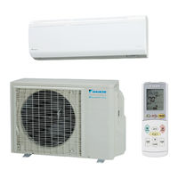
Daikin Quaternity RXG15HVJU Service Manual (252 pages)
Inverter Pair Wall Mounted Type H-Series
Brand:
Daikin
| Category:
Air Conditioner
| Size: 21 MB
Table of Contents
Table of Contents
2
Safety Considerations
7
Part 1
10
Part
10
List of Functions
10
Functions
11
Part 2
12
Specifications
12
Specifications
13
Part 3
16
Printed Circuit Board
16
Connector Wiring Diagram
16
Part
16
Printed Circuit Board Connector Wiring Diagram
17
Indoor Unit
17
Outdoor Unit
19
Part 4
20
Function and Control
20
Description of Operation
21
Indoor Unit
21
Outdoor Unit
22
Main Functions
23
QUATERNITY Drying Operation
23
Comfort Sleep Operation
25
Automatic Operation
27
Comfort Airflow Mode
28
Cooling Breeze Operation
29
Power-Airflow Dual Flapsfins
30
Wide-Angle Louversfins
30
Power-Airflow Dual Flaps
30
Wide-Angle Louvers
30
3-D Airflow
31
POWERFUL Operation
32
Indoor Unit Quiet Operation
32
Multi-Colored Indicator Lamp
33
Monitor Brightness Setting
33
Indoor Unit Quiet Operation
33
Information Display
34
Monitor Brightness Setting
34
Mold-Proof Stick
35
FLASH STREAMER AIR PURIFYING Operation
36
Wipe-Clean Flat Panel
38
Filter Cleaning Indicator (Remote Controller)
39
TIMER Operation
39
Night Set Mode
40
Table for Special Modes
41
Thermostat Control
42
Fan Speed Control for Indoor Units
43
Draft Prevention (Hot-Start)
45
Control Specification
46
Frequency Control
46
Preheating Operation (Quick Warming Function)
47
Four Way Valve Operation
47
Four-Way Valve Operation
47
Compressor Start-Up Protection
48
Fan Speed Control for Outdoor Unit
49
Fin Thermistor Control
50
Input Current Control
50
Peak-Cut Control
51
Indoor Heat Exchanger Freeze-Up Protection
52
Dew Prevention
53
Liquid Compression Protection 2
54
Discharge Pipe Temperature Control
54
Automatic Defrosting
55
Electronic Expansion Valve Control
56
Power Initialization Control
57
Pressure Equalization Control
60
Part 5
62
System Configuration
62
Installation Manual
63
Indoor Units
63
Installation Tips
64
Drain Hose
65
Indoor Unit Installation
66
Wall Embedded Piping
68
Drain Piping
70
Refrigerant Piping Work
71
Outdoor Units
73
Installing Outdoor Unit
74
Outdoor Unit Installation
75
Pump down Operation
76
Test Run and Final Check
78
System Configuration
79
Instruction
80
Remote Controller
80
Cooling · QUATERNITY DRYING Operation
82
Heating Operation
83
AUTO Operation
84
FLASH STREAMER AIR PURIFYING · POWERFUL Operation
85
Adjusting Airflow Direction · Airflow Rate
86
COMFORT AIRFLOW · COOLING BREEZE Operation
87
TIMER Operation
88
COMFORT SLEEP Operation
89
Set up · Child Proof Lock
90
Information Display
91
Service Diagnosis
92
Convenient Service Check Function
94
Troubleshooting
96
Error Code Indication by Remote Controller
96
Air Conditioner Does Not Run
97
Air Conditioner Runs but Does Not Cool or Heat
100
When Operation Starts, Safety Breaker Trips
102
Air Conditioner Makes a Loud Sound and Vibrates
104
Indoor Unit PCB Abnormality
105
Peak-Cut Control or Freeze-Up Protection
106
Fan Motor System (DC Motor) Abnormality
108
Streamer Unit Abnormality
110
Thermistor System Abnormality
112
Front Panel Open / Close Abnormality
113
Humidity Sensor Abnormality
114
Signal Transmission Error (Indoor Unit - Outdoor Unit)
115
Incompatible Power Supply between Indoor Unit and Outdoor Unit
117
Outdoor Unit PCB Abnormality
118
OL Activation (Compressor Overload)
119
Compressor Lock
120
DC Fan Lock
121
Input Overcurrent Detection
122
Four-Way Valve Abnormality
124
Discharge Pipe Temperature Control
126
High Pressure Control in Cooling
127
Part
128
Compressor Sensor System Abnormality
129
Position Sensor Abnormality
130
DC Voltage / DC Current Sensor Abnormality
132
Thermistor System Abnormality
133
Abnormal Temperature in Electrical Box
135
Temperature Rise in Radiation Fin
137
Output Overcurrent
139
Insufficient Gas
141
Over Voltage Protection / Low Voltage Protection
143
Outdoor Unit PCB Abnormality or Communication Circuit Abnormality135
144
Outdoor Unit PCB Abnormality or Communication Circuit Abnormality
144
Signal Transmission Error on Outdoor Unit PCB
147
Lights-Out of Microcomputer Status Lamp
149
Check
150
Thermistor Resistance Check
150
Installation Condition Check
151
Outdoor Fan System Check (DC Motor)
151
Power Supply Waveform Check
152
Main Circuit Electrolytic Capacitor Check
152
Refrigerant System Check
153
Inverter Checker" Check
154
Power Transistor Check
155
Discharge Pressure Check
156
Electronic Expansion Valve Check
157
Indoor Unit PCB Output Check
158
Rotating Pulse Input on Outdoor Unit PCB Check
159
Humidity Sensor Check
160
Main Circuit Short Check
160
Four-Way Valve Performance Check
161
Solenoid Valve for Dehumidification Check
162
Part 7
164
Removal Procedure
164
Indoor Unit
165
Removal of Air Filters / Front Panel
165
Removal Procedure Part
165
Removal of Upper Panel
172
Removal of Front Grille
175
Removal of Assembly of Open/Close Mechanism
178
Removal of Assembly of Reduction Motor
180
Removal of Electrical Box
183
Removal of PCB
188
Removal of Dehumidifying Solenoid Valve Coil
194
Removal of Drain Hose
195
Removal of Swing Motor
197
Removal of Swing Motor
198
Removal of Heat Exchanger
199
Removal of Propeller Fan / Fan Motor
202
Removal of Horizontal Blades / Vertical Blades
205
Removal of Streamer Unit
208
Outdoor Unit
212
How to Check the Service Monitor (LED A)
212
Removal of Propeller Fan / Fan Motor
214
Removal of Electrical Box
219
Removal of PCB
223
Removal of Sound Blanket
227
Removal of Thermistor Assembly
229
Removal of Reactor / Partition Plate
231
Removal of Four Way Valve
233
Removal of Four-Way Valve
233
Removal of the Expansion Valve
235
Removal of Compressor
237
Part 8
240
Others Additional Information
240
Additional Information
241
Trial Operation
241
Field Setting
242
Jumper Setting
242
Application of Silicon Grease to a Power Transistor and a Diode Bridge234
243
Application of Silicon Grease to a Power Transistor and a Diode Bridge
243
Part 9
244
Appendix
244
Piping Diagrams
245
Indoor Units
245
Outdoor Units
245
Wiring Diagrams
246
Indoor Units
246
Outdoor Units
246
Part
246
Index
248
Advertisement
Daikin Quaternity RXG15HVJU Engineering Data (80 pages)
H Series Split-System Room Air Conditioners
Brand:
Daikin
| Category:
Air Conditioner
| Size: 9.6 MB
Table of Contents
Table of Contents
2
Quaternity FTXG12HVJU RXG12HVJU
3
1 Power Supply
3
Ftxg09Hvju Rxg09Hvju
3
Ftxg15Hvju Rxg15Hvju
3
2 Functions
4
3 Specifications
5
4 Dimensions
7
5 Wiring Diagrams
8
6 Piping Diagrams
9
7 Capacity Tables
10
Heat Pump
10
8 Operation Limit
16
9 Sound Level
17
Measuring Location
17
Octave Band Level
18
Outdoor Units
19
10 Electric Characteristics
20
11 Installation Manual
21
Indoor Units
21
Choosing an Installation Site
22
Indoor Unit
22
Wireless Remote Controller
22
Indoor Unit Installation Drawings
23
Installation Tips
24
Drain Hose
25
Indoor Unit Installation
26
Wall Embedded Piping
28
Drain Piping
30
Refrigerant Piping Work
31
Outdoor Units
33
Precautions on Installation
35
Installation Guidelines
35
Installing Outdoor Unit
36
Outdoor Unit Installation
37
Pump down Operation
38
Test Run and Final Check
40
12 Operation Manual
41
Dry Operation
49
Operation Manual
53
13 Optional Accessories
71
Option List
71
Installation Manual
72
Safety Precautions
76
Switch Settings
77
Before Installation
78
Installation Procedure
78
Daikin Quaternity RXG15HVJU Engineeiring Data (80 pages)
H-Series Split-System Room Air Conditioners
Brand:
Daikin
| Category:
Heat Pump
| Size: 8.9 MB
Table of Contents
Table of Contents
2
Quaternity
3
1 Power Supply
3
Ftxg09Hvju Rxg09Hvju
3
Ftxg12Hvju
3
Ftxg15Hvju Rxg15Hvju
3
2 Functions
4
3 Specifications
5
4 Dimensions
7
5 Wiring Diagrams
8
6 Piping Diagrams
9
7 Capacity Tables
10
Heat Pump
10
8 Operation Limit
16
9 Sound Level
17
Measuring Location
17
Octave Band Level
18
Outdoor Units
19
10 Electric Characteristics
20
11 Installation Manual
21
Indoor Units
21
Indoor Unit Installation
27
Drain Piping
31
Refrigerant Piping Work
32
Outdoor Units
34
Precautions on Installation
35
Installation Guidelines
35
Pump down Operation
38
12 Operation Manual
41
13 Optional Accessories
72
Option List
72
Installation Manual
73
Safety Precautions
77
Before Installation
79
Advertisement
Daikin Quaternity RXG15HVJU Service Manual (26 pages)
Outdoor Unit Removal Procedure
Brand:
Daikin
| Category:
Heat Pump
| Size: 3.45 MB
Table of Contents
Table of Contents
3
Removal of Outdoor Fan / Fan Motor
4
Removal of Electrical Box
8
Removal of PCB
12
Removal of Sound Blankets
15
Removal of Thermistor Assembly
17
Removal of Reactor / Partition Plate
19
Removal of Four Way Valve
20
Removal of Electronic Expansion Valve
22
Removal of Compressor
23
Advertisement
Related Products
Daikin Quaternity RXG12HVJU
Daikin RXG50K3V1B
Daikin RX-GV
Daikin RXG25CVMA
Daikin RXG35CVMA
Daikin RXG25CVMB
Daikin RXG35CVMB
Daikin RXG35J2V1B
Daikin RXG35E3V1B
Daikin RXG25E3V1B
Daikin Categories
Air Conditioner
Heat Pump
Remote Control
Chiller
Fan
More Daikin Manuals
Login
Sign In
OR
Sign in with Facebook
Sign in with Google
Upload manual
Upload from disk
Upload from URL