Sign In
Upload
Manuals
Brands
Compaq Manuals
Desktop
Compaq Portable II
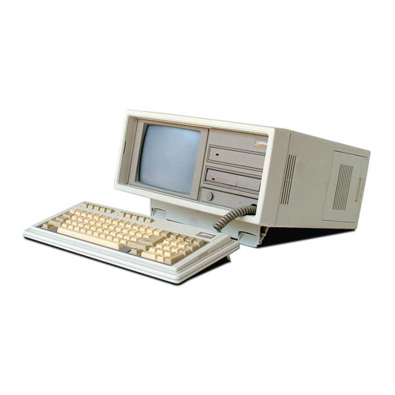
Compaq Compaq Portable II Manuals
Manuals and User Guides for Compaq Compaq Portable II. We have
1
Compaq Compaq Portable II manual available for free PDF download: Maintenance And Service Manual
Compaq Compaq Portable II Maintenance And Service Manual (119 pages)
Personal Computer
Brand:
Compaq
| Category:
Desktop
| Size: 1.08 MB
Table of Contents
Notice
1
Caution
2
Optional Tools
2
Tools and Supplies
2
Personal Computer
3
Warning
3
Introduction
4
Operating and Performance Specifications
4
System Unit
4
Keyboard
5
Megabyte Fixed Disk Drive
5
Video Display Unit
5
360 Kbyte Diskette Drive
6
Megabyte Diskette Drive
6
1.44 Megabyte Diskette Drive Specifications
7
Power Supply
7
Power on Self Test
8
Power on Self Test/Problem Isolation
8
System Problem Isolation
8
Setup
11
Chapter 4. Diagnostic Procedures
12
Error Messages and Codes
13
Power on Self Test Messages
13
Chapter 5.2 Diagnostics Error Codes
14
Processor Test Error Codes
15
Recommended Action
16
CMOS RAM Test Failed
17
Speaker Test Failed
18
Memory Related Error Codes
32
Memory Configurations
32
Version 1 System Board Using 64K Rams (0 - 256 Kbytes)
34
Compaq Portable II Personal Computer
40
Chapter 6. Illustrated Parts Catalog
40
Chassis
41
COMPAQ PORTABLE II Personal Computer Chassis
41
Common Chassis
42
COMPAQ PORTABLE II Personal Computer Common Chassis
42
COMPAQ PORTABLE II Personal Computer Mechanical Chassis
45
Chapter 6.4 Mechanical Chassis
45
COMPAQ PORTABLE II Personal Computer Monitor
46
Chapter 6.6 Cable Kit
46
Chapter 6.7 Miscellaneous Hardware Kit
47
Chapter 7. Removal and Replacement Procedures
48
Disconnecting the AC Power Cord
49
Locating the Line Filter On/Off Switch Assembly
49
Chapter 7.2 AC Power Fuse
49
Outer Access Casing
51
Replacing the AC Power Fuse
51
Removing the Outer Access Casing
53
Chapter 7.4 Keyboard Assembly
53
Disconnecting the Keyboard Connector from the System Board
54
Returning the Computer to a Flat Position on the Work Surface
54
Removing the Keyboard
55
Chapter 7.5 Front Bezel
55
Removing the Brightness Control Knob
56
Placing the Computer in an Upward Position
56
Removing the Six Front Bezel Mounting Screws
57
Removing the Front Bezel
57
Positioning the Computer
58
Loosening the Mine Power Supply Mounting Screws
59
Removing the Power Supply Mounting Screws
60
Removing the Power Supply
60
Disconnecting Fan Assembly and Automatic Power Switching Connectors
61
Chapter 7.7 Fan Assembly
61
Automatic Power Switching Board (APS)
62
Removing the Fan Assembly
62
Automatic Power Switching
63
High Voltage Access Plate
64
Tying Together the Harness Wires
64
Board Slots Access Plate
65
Mass Storage Device Access Plate
66
Removing the Board Slots Access Plate
66
System Memory Board Access Plate
67
Removing the Mass Storage Device Access Plate
67
Exposing the System Memory Board Access Plate
68
Removing the System Memory Board Access Plate
68
Cable Tray Access Plate
69
Exposing the Cable Tray Access Plate
69
Multipurpose Controller Board
70
Removing the Cable Tray Access Plate
70
Locating the Multipurpose Controller Board
71
Disconnecting the Mass Storage Device Signal Cables
71
Video Display Controller Board
72
Removing the Multipurpose Controller Board
72
Locating the Video Display Controller Board
72
512/2048 Kbyte Memory Expansion Board
74
Removing the Video Display Controller Board
74
Handle
75
Removing the Handle
76
Chapter 7.18 System Board
76
Disconnecting the Mass Storage Device Power Cable
78
Disconnecting the Keyboard Power, VDU Power
78
Removing the System Board
79
Chapter 7.19 Battery
79
512/1536 Kbyte System Memory Board
80
Removing the Battery
80
Chapter 7.21 Memory Option
81
Mass Storage Device Subassembly
85
Replacing a Memory Chip
85
Mass Storage Device Subassembly Enclosure
86
Removing the Drive Bezel from the Front Bezel
87
Removing the Mass Storage Device Subassembly Enclosure Mounting Screws
87
To Remove the Fixed Disk Drive Assembly
89
Removing the Fixed Disk Drive
90
Diskette Drive
90
Speaker and Brightness Potentiometer
91
Removing the Diskette Drive
91
Removing the Brightness Potentiometer
92
Chapter 7.24 Video Display Unit
92
Disconnecting the VDU Power Cable
93
Returning the Computer to Flat Position on the Work Surface
93
Disconnecting the VDU Signal Cable
94
Disconnecting and Removing the VDU High Voltage Cable
95
Removing the VDU Sweep Board
95
Removing the Four VDU Mounting Screws
96
Removing the Video Display Unit from the System Chassis
96
Jumper Settings, Switch Settings, and Adjustments
98
System Board Jumper Settings
98
512/2048 Kbyte Memory Expansion Board Jumper Settings
100
360 Kbyte Diskette Drive Switch Settings
101
Multipurpose Controller Board Switch Settings
102
Multipurpose Controller Board Switch and Jumper Settings
102
Chapter 8.5 Fixed Disk Drive Controller Board
105
Video Display Controller Board Jumper Settings
106
Serial/Parallel Interface Board Switch Settings
111
Video Display Unit Adjustments
112
CRT Adjustment Procedure
112
Standard Working Position
113
Location of Brightness Control Knob
114
Adjusting the CRT BRITE Control
114
Adjusting the CRY Width Control
115
Adjusting the Focus Control
116
Character Height Adjustment
116
Advertisement
Advertisement
Related Products
Compaq iPAQ IA-2
Compaq iPAQ IA-1
Compaq IQ525 - TouchSmart - 4 GB RAM
Compaq IQ526 - TouchSmart - 4 GB RAM
Compaq IQ527 - TouchSmart - 4 GB RAM
Compaq iPAQ 1.0
Compaq iPAQ 1.2
Compaq iPAQ 2.0
Compaq iPAQ Series
Compaq ISS Technology Update, Volume 7, Number 9
Compaq Categories
Desktop
Laptop
Server
Monitor
Storage
More Compaq Manuals
Login
Sign In
OR
Sign in with Facebook
Sign in with Google
Upload manual
Upload from disk
Upload from URL