Sign In
Upload
Manuals
Brands
Citizen Manuals
Cutter
CL-E720DT
Citizen CL-E720DT Manuals
Manuals and User Guides for Citizen CL-E720DT. We have
2
Citizen CL-E720DT manuals available for free PDF download: Technical Manual, User Manual
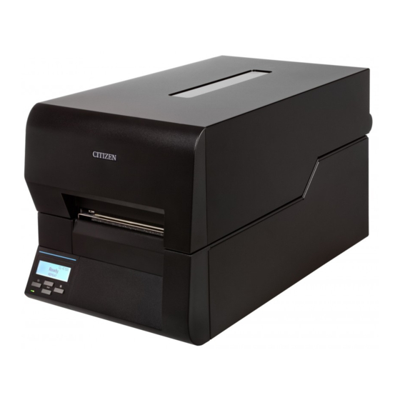
Citizen CL-E720DT Technical Manual (189 pages)
direct thermal barcode & label printer
Brand:
Citizen
| Category:
Label Maker
| Size: 18.1 MB
Table of Contents
English
6
Safety Precautions
4
Chapter 1 Specifications
7
General Specifications
7
Printable Area
12
Printing Position Accuracy
13
Adjustable Sensors
14
Table of Contents
16
Chapter 2 Operating Principles
18
Operation of each Mechanism
18
Locations and Functions of Major Electrical Parts
18
Media Feed/Printing Mechanism
19
Label/Tag Detection Mechanism
20
Print Head Up/Down Detection Mechanism
23
Head Balance Adjustment Mechanism
24
Media Thickness Adjustment Mechanism
25
Operation of Control Parts
26
Configuration of Printer
26
Filter & Power Supply Section
26
Operation Panel (SA Opepane PCB)
26
SA Main PCB
26
Motor
27
Parallel I/F (IEEE1284) (Option)
27
Sensors
27
Serial I/F (RS-232C) (Option)
27
Thermal Print Head
27
USB I/F (USB2.0 Compatible Full-Speed Mode/High-Speed Mode)
27
Wired LAN I/F
27
Wireless LAN I/F (Option)
27
Operation of Control Unit
28
Buzzer
29
Cpu
29
Flash ROM
29
Fpga
29
Head Control
29
SDRAM (Synchronous Dynamic RAM)
29
Stepping Motor Driver (for "SA PF Motor")
29
Memory Map
30
Sensors
31
Head up Sensor (SA Head up Sensor PCB)
31
Transparent Sensor (SA TRA Sen PCB) and Reflective Sensor (SA Ref Sensor PCB)
32
Head Temperature Sensor
34
PF Motor Temperature Sensor
35
Drivers
37
PF Motor Driver
37
Head Driver
38
Buzzer Driver
39
Other Circuits
40
Power Supply Circuit
40
Reset Circuit
41
Clock Circuit
42
Ope-Pane Circuit
43
USB I/F Control Circuit
44
Wired LAN I/F Circuit
45
Option Board I/F Circuit (Option)
46
Peeler Circuit (for Optional Peeler)
47
Cutter Control Circuit (for Optional Cutter)
48
Operation Panel
50
External View
50
Keys
50
Lcd
50
LED (Green/Red)
50
Test Mode
52
Self Print Mode
52
Hex Dump Mode
53
Menu List Print Mode
54
Factory/Service Mode
56
How to Enter Factory/Service Mode
56
How to Print the Factory Mode Settings Menus
58
Machine Information
59
How to Change the Settings in Factory Mode
61
Submenu Table in Factory Mode
61
Setting Submenu in Factory Mode
64
How to Operate Submenus in Service Mode
65
Submenu Table in Service Mode
65
Submenu Operation in Service Mode
66
Interface
68
USB Interface
68
Signal Line and Pin Arrangement
68
Specifications
68
Wired LAN Interface
68
Serial Interface (Option)
69
Signal Line and Pin Assignment
69
Specifications
69
Protocol
70
Parallel Interface (Option)
71
Signal Line and Pin Assignment
71
Specifications
71
Compatible Timing Specification
72
Parallel Port Status Signals When an Error Occurs
72
Chapter 3 Disassembly and Maintenance
78
Maintenance Precautions
78
Cleaning
79
Lubrication
79
Lubrication Frequency
79
Types of Lubricant
79
Quantity of Lubricant
79
Maintenance Tools List
80
Quick Detachment of Major Parts
81
SA Head
81
SA Platen
82
Disassembly, Reassembly and Lubrication
83
SA Top Cover" Block
84
SA Top Cover
84
Cover PF Motor
85
SA Opepane PCB
86
Unit Opepane
86
Case
87
SA Main PCB" and "SA Relay PCB
88
SA Main PCB" Connectors
88
Unit Mechanism
90
Unit Power Supply" and "Paper Holder" Block
91
Unit Power Supply" Block and "Paper Holder" Block
91
Plate Holder Paper L
92
Unit Power Supply
92
SA Power SW Cable" and "Frame Bottom
93
SA Platen
94
Leaf Adjust Sensor U
95
Unit Sensor U" and "SA Head up Sensor PCB
95
SA TRA Sen PCB
96
FFC TRA Sensor" and "Leaf Adjust Sensor U
97
Unit Head" and "Unit PF
100
SA Head" Block
102
SA Head", "Cam Head Adjust" and "Cam Head Balance
102
SA Head" and "Cam Head Adjust
104
Cam Head Balance
106
SA PF Motor
107
SA Ref Sensor PCB" and "Spring Adjust Sensor L
108
Platen Drive Gears
110
Lever Head Lock" and "SA Main Plate R
111
Adjustment (Transparent/Reflective Sensor)
113
Sensor Position Adjustment (Factory Mode)
113
Sensor Sensitivity Adjustment (Factory Mode)
113
Init Thru Sen" Sensitivity Adjustment
114
Init Refl Sen Sensitivity Adjustment
116
Chapter 4 Troubleshooting
121
Error Message and Corrective Actions
121
Troubleshooting
123
Problems in Powering up the Printer
123
Media-Feed Problems
124
Problems in Printing
125
Sensor Problems
126
Operation Panel Problems
129
Connector Location
130
Unknown
165
Chapter 6 . Circuit Diagrams
166
Inter Connection
166
SA Main PCB (1, 2/12) [CPU (1)]
167
SA Main PCB (3/12) [CPU (2)]
168
SA Main PCB (4/12) [ROM, SDRAM]
169
SA Main PCB (5/12) [FPGA]
170
SA Main PCB (6/12) [Head, Opepane & Buzzer]
171
SA Main PCB (7/12) [Ribbon, Cutter & Peeler]
172
SA Main PCB (8/12) [PF Motor Drive & Option I/F]
173
SA Main PCB (9/12) [Media Sensors & Head up Sensor]
174
SA Main PCB (10/12) [USB I/F & DAC]
175
SA Main PCB (11/12) [Power Supply]
176
SA Main PCB (12/12) [LAN I/F]
177
SA Opepane PCB
178
SA Relay PCB
179
SA Ref Sensor PCB
180
SA TRA Sen PCB
181
SA Head up Sensor PCB
182
Mounting Diagrams
185
A-1. SA Main PCB
185
A-2. SA Opepane PCB
187
A-3. SA Relay PCB
187
A-4. SA Ref Sensor PCB
187
A-5. SA TRA Sen PCB
187
A-6. SA Head up Sensor PCB
188
Advertisement
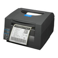
Citizen CL-E720DT User Manual (16 pages)
CL-S52 series; CL-S53 series; CL-S62 series; CL-S63 series
Brand:
Citizen
| Category:
Cutters
| Size: 1.69 MB
Table of Contents
Table of Contents
2
Notice
3
SAFETY SIGNS that Must be Strictly Observed
4
Function
6
Main Specifications of Auto-Cutter
6
Checking Items Inside the Accessory Box
7
Auto-Cutter Settings
8
Cut Position
10
Cut Settings
11
Auto Cut-Length Detection
12
User Maintenance
13
Troubleshooting
15
Advertisement
Related Products
Citizen CL-E700 Series
Citizen CL-E720
Citizen CL-E730
Citizen CL-E321
Citizen CL-E331
Citizen CL-E321EX
Citizen CL-E331EX
Citizen CL-E300
Citizen CL-E303
Citizen CL-E300EX
Citizen Categories
Watch
Printer
Calculator
Blood Pressure Monitor
Label Maker
More Citizen Manuals
Login
Sign In
OR
Sign in with Facebook
Sign in with Google
Upload manual
Upload from disk
Upload from URL