Sign In
Upload
Manuals
Brands
Cirrus Logic Manuals
Controller
CS44800
Cirrus Logic CS44800 Manuals
Manuals and User Guides for Cirrus Logic CS44800. We have
1
Cirrus Logic CS44800 manual available for free PDF download: Manual
Cirrus Logic CS44800 Manual (80 pages)
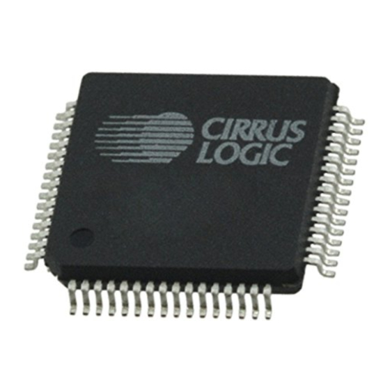
8-Channel Digital Amplifier Controller
Brand:
Cirrus Logic
| Category:
Controller
| Size: 1 MB
Table of Contents
Table of Contents
3
1 Characteristics and Specifications
8
Specified Operating Conditions
8
Absolute Maximum Ratings
8
DC Electrical Characteristics
9
Digital Interface Characteristics
9
Pwm Output Performance Characteristics
10
Figure 1.Performance Characteristics Evaluation Active Filter Circuit
10
Pwm Filter Characteristics
11
Switching Characteristics - Xti
11
Figure 2.XTI Timings
11
Switching Characteristics - Sys_Clk
12
Switching Characteristics - Pwmouta1-B4
12
Switching Characteristics - Ps_Sync
12
Figure 3.SYS_CLK Timings
12
Figure 4.Pwmoutxx Timings
12
Figure 5.PS_SYNC Timings
12
Switching Characteristics - Dai Interface
13
Figure 6.Serial Audio Interface Timing
13
Figure 7.Serial Audio Interface Timing - TDM Mode
13
Switching Characteristics - Control Port - I²C Format
14
Figure 8.Control Port Timing - I²C Format
14
Switching Characteristics - Control Port - Spi Format
15
Figure 9.Control Port Timing - SPI Format
15
2 Pin Descriptions
16
Figure 10.CS44800 Pinout Diagram
16
I/O Pin Characteristics
20
3 Typical Connection Diagrams
21
Figure 11.Typical Full-Bridge Connection Diagram
21
Figure 12.Typical Half-Bridge Connection Diagram
22
4 Applications
23
Overview
23
Feature Set Summary
23
Clock Generation
24
Figure 13.CS44800 Data Flow Diagram (Single Channel Shown)
24
Figure 14.Fundamental Mode Crystal Configuration
25
Fsin Domain Clocking
25
Fsout Domain Clocking
25
Table 1. Common DAI_MCLK Frequencies
25
Figure 15.3Rd Overtone Crystal Configuration
26
Figure 16.CS44800 Internal Clock Generation
26
Fsin Clock Domain Modules
27
Digital Audio Input Port
27
Table 2. DAI Serial Audio Port Channel Allocations
27
Figure 17.I²S Serial Audio Formats
28
Figure 18.Left-Justified Serial Audio Formats
28
Figure 19.Right-Justified Serial Audio Formats
29
Figure 20.One Line Mode #1 Serial Audio Format
29
Figure 21.One Line Mode #2 Serial Audio Format
30
Figure 22.TDM Mode Serial Audio Format
30
Auto Rate Detect
31
Emphasis
31
Figure 23.De-Emphasis Curve
31
Fsout Clock Domain Modules
32
Sample Rate Converter
32
Load Compensation Filter
32
Digital Volume and Mute Control
32
Table 3. Load Compensation Example Settings
32
Peak Detect / Limiter
33
PWM Engines
33
Interpolation Filter
34
Quantizer
34
Modulator
34
PWM Outputs
34
Table 4. Typical PWM Switch Rate Settings
34
4.5.10 Power Supply Rejection (PSR) Real-Time Feedback
35
Control Port Description and Timing
36
SPI Mode
36
Figure 24.Control Port Timing in SPI Mode
36
I²C Mode
37
Figure 25.Control Port Timing, I²C Slave Mode Write
37
Figure 26.Control Port Timing, I²C Slave Mode Read
37
Gpios
38
Host Interrupt
38
5 Power Supply, Grounding, and Pcb Layout
39
Figure 27.Recommended CS44800 Power Supply Decoupling Layout
39
Figure 28.Recommended CS44800 Crystal Circuit Layout
40
Figure 29.Recommended PSR Circuit Layout
41
Reset and Power-Up
42
PWM Popguard® Transient Control
42
Recommended Power-Up Sequence
42
Recommended PSR Calibration Sequence
43
Recommended Power-Down Sequence
44
Figure 30.PSR Calibration Sequence
44
6 Register Quick Reference
46
7 Register Description
50
Memory Address Pointer (MAP)
50
Increment (INCR)
50
Memory Address Pointer (Mapx)
50
CS44800 I.D. and Revision Register (Address 01H) (Read Only)
50
Chip I.D. (Chip_Idx)
50
Chip Revision (Rev_Idx)
50
Clock Configuration and Power Control (Address 02H)
51
Enable SYS_CLK Output (EN_SYS_CLK)
51
SYS_CLK Clock Divider Settings (SYS_CLK_DIV[1:0])
51
PWM Master Clock Divider Settings (PWM_MCLK_DIV[1:0])
51
Power down XTAL (PDN_XTAL)
51
Power down Output Mode (PDN_OUTPUT_MODE)
52
Power down (PDN)
52
PWM Channel Power down Control (Address 03H)
52
Power down PWM Channels (PDN_PWMB4:PDN_PWMA1)
52
Misc. Configuration (Address 04H)
53
Digital Interface Format (DIFX)
53
AM Frequency Hopping (AM_FREQ_HOP)
53
Freeze Controls (FREEZE)
53
Table 5. Digital Audio Interface Formats
53
Emphasis Control (DEM[1:0])
54
Ramp Configuration (Address 05H)
54
Ramp-Up/Down Setting (RAMP[1:0])
54
Ramp Speed (RAMP_SPD[1:0])
54
Volume Control Configuration (Address 06H)
55
Single Volume Control (SNGVOL)
55
Soft Ramp and Zero Cross Control (SZC[1:0])
55
Enable 50% Duty Cycle for Mute Condition (MUTE_50/50)
55
Soft Ramp-Down on Interface Error (SRD_ERR)
56
Soft Ramp-Up on Recovered Interface Error (SRU_ERR)
56
Auto-Mute (AMUTE)
56
Master Volume Control - Integer (Address 07H)
57
Master Volume Control - Integer (MSTR_IVOL[7:0])
57
Master Volume Control - Fraction (Address 08H)
57
Master Volume Control - Fraction (MSTR_FVOL[1:0])
57
Table 6. Master Integer Volume Settings
57
Table 7. Master Fractional Volume Settings
58
Channel XX Volume Control - Integer (Addresses 09H - 10H)
59
Channel Volume Control - Integer (Chxx_Ivol[7:0])
59
Channel XX Volume Control1 - Fraction (Address 11H)
59
Channel XX Volume Control2 - Fraction (Address 12H)
59
Channel Volume Control - Fraction (CHXX_FVOL[1:0])
59
Table 8. Channel Integer Volume Settings
59
Channel Mute (Address 13H)
60
Independent Channel Mute (CHXX_MUTE)
60
Channel Invert (Address 14H)
60
Invert Signal Polarity (CHXX_INV)
60
Table 9. Channel Fractional Volume Settings
60
Peak Limiter Control Register (Address 15H)
61
Peak Signal Limit All Channels (LIMIT_ALL)
61
Peak Signal Limiter Enable (LIMIT_EN)
61
Limiter Attack Rate (Address 16H)
61
Attack Rate (ARATE[7:0])
61
Limiter Release Rate (Address 17H)
62
Release Rate (RRATE[7:0])
62
Chnl XX Load Compensation Filter - Coarse Adjust (Addresses 18H, 1Ah, 1Ch, 1Eh, 20H, 22H, 24H, 26H)
62
Channel Compensation Filter - Coarse Adjust (CHXX_CORS[5:0])
62
Table 10. Limiter Attack Rate Settings
62
Table 11. Limiter Release Rate Settings
62
Chnl XX Load Compensation Filter - Fine Adjust (Addresses 19H, 1Bh, 1Dh, 1Fh, 21H, 23H, 25H, 27H)
63
Channel Compensation Filter - Fine Adjust (CHXX_FINE[5:0])
63
Interrupt Mode Control (Address 28H)
63
Interrupt Pin Control (INT1/INT0)
63
Table 12. Channel Load Compensation Filter Coarse Adjust
63
Table 13. Channel Load Compensation Filter Fine Adjust
63
Overflow Level/Edge Select (OVFL_L/E)
64
Interrupt Mask (Address 29H)
64
Interrupt Status (Address 2Ah) (Read Only)
64
SRC Unlock Interrupt (SRC_UNLOCK)
64
SRC Lock Interrupt (SRC_LOCK)
65
Ramp-Up Complete Interrupt (RMPUP_DONE)
65
Ramp-Down Complete Interrupt (RMPDN_DONE)
65
Mute Complete Interrupt (Mute_Done)
65
Channel over Flow Interrupt (OVFL_INT)
65
GPIO Interrupt Condition (GPIO_INT)
65
Channel over Flow Status (Address 2Bh) (Read Only)
66
7.23.1 Chxx_Ovfl
66
GPIO Pin In/Out (Address 2Ch)
66
GPIO In/Out Selection (GPIOX_I/O)
66
GPIO Pin Polarity/Type (Address 2Dh)
66
GPIO Polarity/Type Selection (GPIOX_P/T)
66
GPIO Pin Level/Edge Trigger (Address 2Eh)
67
GPIO Level/Edge Input Sensitive (GPIOX_L/E)
67
GPIO Status Register (Address 2Fh)
67
GPIO Pin Status (GPIOX_STATUS)
67
GPIO Interrupt Mask Register (Address 30H)
68
GPIO Pin Interrupt Mask (M_GPIOX)
68
PWM Configuration Register (Address 31H)
68
Over Sample Rate Selection (OSRATE)
68
Channels A1 and B1 Output Configuration (A1/B1_OUT_CNFG)
68
Channels A2 and B2 Output Configuration (A2/B2_OUT_CNFG)
68
Channel A3 Output Configuration (A3_OUT_CNFG)
69
Channel B3 Output Configuration (B3_OUT_CNFG)
69
Channels A4 and B4 Output Configuration (A4/B4_OUT_CNFG)
69
PWM Minimum Pulse Width Register (Address 32H)
69
Disable PWMOUTXX - Signal (DISABLE_PWMOUTXX-)
69
Minimum PWM Output Pulse Settings (MIN_PULSE[4:0])
70
PWMOUT Delay Register (Address 33H)
70
Differential Signal Delay (DIFF_DLY[2:0])
70
Channel Delay Settings (CHNL_DLY[4:0])
70
Table 14. PWM Minimum Pulse Width Settings
70
Table 15. Differential Signal Delay Settings
70
Table 16. Channel Delay Settings
71
Figure 31.PWM Output Delay
72
PSR and Power Supply Configuration (Address 34H)
73
Power Supply Rejection Enable (PSR_EN)
73
Power Supply Rejection Reset (PSR_RESET)
74
Power Supply Rejection Feedback Enable (FEEDBACK_EN)
74
Power Supply Sync Clock Divider Settings (PS_SYNC_DIV[2:0])
74
Decimator Shift/Scale (Addresses 35H, 36H, 37H)
74
Decimator Shift (DEC_SHIFT[2:0])
74
Table 17. Power Supply Sync Clock Divider Settings
74
Decimator Scale (DEC_SCALE[18:0])
75
Decimator Outd (Addresses 3Bh, 3Ch, 3Dh)
75
Decimator Outd (DEC_OUTD[23:0])
75
Table 18. Decimator Shift/Scale Coefficient Calculation Examples
75
8 Parameter Definitions
76
9 References
77
10 Package Dimensions
78
Figure 32.64-Pin LQFP Package Drawing
78
11 Thermal Characteristics
79
12 Ordering Information
79
13 Revision History
79
Advertisement
Advertisement
Related Products
Cirrus Logic CS44600
Cirrus Logic CS44600-CQZ
Cirrus Logic CS44600-DQZR
Cirrus Logic CS44600-DQZ
Cirrus Logic CS44600-CQZR
Cirrus Logic Crystal LAN CS8900A
Cirrus Logic Crystal LAN CS8900A-IQ
Cirrus Logic Crystal LAN CS8900A-CQ3
Cirrus Logic Crystal LAN CS8900A-IQ3
Cirrus Logic Crystal LAN CS8900A-CQ
Cirrus Logic Categories
Computer Hardware
Motherboard
Conference System
Media Converter
Controller
More Cirrus Logic Manuals
Login
Sign In
OR
Sign in with Facebook
Sign in with Google
Upload manual
Upload from disk
Upload from URL