Sign In
Upload
Manuals
Brands
Carrier Manuals
Chiller
PIC 5+
Carrier PIC 5+ Manuals
Manuals and User Guides for Carrier PIC 5+. We have
2
Carrier PIC 5+ manuals available for free PDF download: Installation, Operation And Maintenance Instructions, User Manual
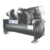
Carrier PIC 5+ Installation, Operation And Maintenance Instructions (116 pages)
Hermetic Centrifugal Liquid Chillers DUAL STAGE
Brand:
Carrier
| Category:
Chiller
| Size: 8.07 MB
Table of Contents
Table of Contents
2
1 Safety Considerations
6
Installation Safety Considerations
6
Maintenance Safety Considerations
6
Operating Checks, Relief Valves
7
Equipment and Components under Pressure
7
Repair Safety Considerations
8
2 Introduction and Chiller Familiarisation
9
Operating Conditions Range
9
Abbreviations and Explanations
9
Chiller Technical Documentation (Wiring Diagram, Dimensional Drawings, PID)
10
CE Marking
10
Classification
10
Chiller Familiarization 19DV
11
Chiller Information Plate
11
System Components
11
Product Identification
12
Refrigeration Cycle
15
Refrigerant Lubrication Cycle
16
Controls
25
Definitions
25
General
25
PIC 5+ System Components
25
Temperature Sensors
29
Pressure Transducers
30
3 Installation
30
Introduction
30
Step 1 - Receive the Machine
30
Inspect the Product Delivered
30
Identify Machine
30
Installation Requirements
33
Provide Machine Protection
34
Operating Environment
34
Step 2 - Rig the Machine
34
Rigging the Complete Machine
34
Rigging the Machine Components
40
Step 3 - Install Machine Supports
41
Install Standard Isolation
41
Installation of Levelling Accessory (if Necessary)
41
Installation of Spring Isolation System
44
Step 4 - Connection of Water, Vent and Purge Piping
45
Install Water Piping to Heat Exchanger
46
Install Vent Piping to Relief Devices
48
Purge Discharge
48
Step 5 - Electrical Connection
48
Connect Control Inputs
49
Connect Control Outputs
49
High Pressure Safety Accessory: SRMCR - Chiller Equipped with VFD LF2
58
VFD Wiring
60
Carrier Comfort Network Interface (CCN)
61
Start-Up/Shut-Down/Recycle Sequence
62
Local Start/Stop Control
62
Lubrication Control
65
Shutdown
66
5 Before Initial Start-Up
67
Necessary Checks
67
Job Data Required
67
Equipment Required
67
Remove Shipping Packaging
68
Lubrication and Purge Circuit Valves
68
Tighten All Gasketed Joints
68
Check Chiller Tightness
69
Standing Vacuum Test
72
8- Chiller Dehydration
72
9- Inspect Water Piping
73
Check Relief Devices
74
Inspect Wiring
74
Ground Fault Troubleshooting
75
Check Purge Compressor Operation
75
Checking the Installation
76
Check Lubrication Circuit System
76
Charge Unit with Refrigerant
77
Software Configuration
78
Input the Design Set Points
78
Input the Local Occupied Schedule
79
Input Service Configurations
79
Field Set up and Verification
86
Perform a Control Test (Quick Calibration / Quick Test)
86
Cooler and Condenser Pressure Transducer and Waterside Flow Device Calibration
87
6 Initial Start-Up
88
Preparation
88
Check Motor Rotation
88
Check Refrigerant Lube
89
To Prevent Accidental Start-Up
89
Check Chiller Operating Condition
89
Instruct the Customer Operator
89
Cooler - Condenser
89
Motor Compressor Assembly
89
Compressor Lubrication System
89
Economizer
89
Control System
89
Purge
89
Surge Prevention Trouble Shooting Guide
90
7 Operating Instructions
92
Operator Duties
92
To Start the Chiller
92
Check the Running System
92
To Stop the Chiller
93
After Limited Shutdown
93
Preparation for Extended Shutdown
93
After Extended Shutdown
93
Cold Weather Operation
93
Manual Guide Vane Operation
94
Service and Operation Log
94
Chiller Idle Requirement
95
Be Idle for a Short Time
95
Be Idle for a Long Time
95
8 Purge Operation Sequence
95
Purge Operating Modes
95
Non-Condensable Gas Pump out
95
Carbon Tank and Regeneration Subsystem
95
9 Maintenance
96
General Maintenance
96
Soldering and Welding
97
Refrigerant Properties
97
Adding Refrigerant
97
Adjusting the Refrigerant Charge
97
Refrigerant Leak Testing
97
Leak Rate
97
Test after Service, Repair, or Major Leak
97
Repair the Leak, Retest, and Apply Standing Vacuum Test
98
Checking Guide Vanes
98
Trim Refrigerant Charge
99
Weekly Maintenance
100
Check the Refrigerant Lubrication System
100
Check for Leaks / Purge Operation
101
Scheduled Maintenance
101
Service on Time
101
Inspect the Control Panel
102
Inspect Purge
102
Purge Unit Maintenance
102
Changing Refrigerant Lubrication Filters
102
Purge Carbon Filter
102
Changing Refrigerant Pump
102
Inspect Refrigerant Float System
103
Inspect Safety Relief Devices and Piping
104
Periodic Check of the Safety Loop
104
Compressor Bearing Maintenance
105
Inspect the Heat Exchanger Tubes and Flow Devices
106
Water Leaks
106
Water Treatment
106
Inspect / Remove the Power Cabinet Equipment
106
Recalibrate Pressure Transducers
108
Recalibrate Temperature Thermistors
108
Corrosion Control
108
Ordering Replacement Chiller Parts
108
10 Trouble Shooting Guide
108
Overview
108
Checking Display Messages
108
Checking Temperature Sensors
108
Resistance Check
109
Voltage Drop Check
109
Check Sensor Accuracy
110
Checking Pressure Transducers
111
High Altitude Locations
112
Quick Test
112
Quick Calibration
112
Pumpdown/Lockout
112
Advertisement
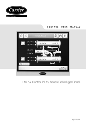
Carrier PIC 5+ User Manual (84 pages)
Control for 19 Series Centrifugal Chiller
Brand:
Carrier
| Category:
Control Systems
| Size: 3.4 MB
Table of Contents
Table of Contents
2
1 Safety Considerations
4
General Description
4
Avoid Electrocution
4
Abbreviations Used
4
2 - General Description
4
3 Hardware Description
5
General Description
5
Sensors
7
Controls Outputs
8
Connections at the User's Terminal Block
8
LEN/CCN Communication Cable Cequirements
11
4 Setting up the User Interface
12
User Interface
12
Web Connection
12
General Features
12
Welcome Screen
12
Synoptic Screen
13
Setpoint Screen
13
On/Off Screen
13
Password/Language Screen
14
Menu Screen
14
Configuration Screen
14
Time Schedule Screen
15
19XR6/7 Status Display Screens
15
19XR2~E/V/D Status Display Screens
17
19DV Status Display Screens
18
5 Series Pic 5+ Control Operation
20
Start/Stop Control
20
Compressor Run Status
20
Chiller Start-Up Sequence
20
Chiller Shutdown Sequence
21
Oil Lubrication Control
21
Refrigerant Lubrication Control
22
Control Point
22
Capacity Control
23
Ramp Loading
24
Surge Correction Control
24
Envelope Control Valve (EC) Control
25
Economizer Damper Valve Control
25
Damper Vapor Source
25
Demand Limit
25
Override Control
26
Recycle Control
27
Running Timers and Counters
27
Water Pumps Control
27
Controls Test
28
Swift Restart
29
Cooling Tower Control
29
Head Pressure Control
29
Ice Build Option
29
Time Schedule
29
Black Box
29
Pressure Transducer Calibration
29
Temperature Sensor Calibration
29
ISM Calibration
30
Alarm Email
30
Prognostic
30
Master Slave Control
31
Oil EXV Control
31
Pumpdown/Lockout
31
Trending
31
Electronic Document
32
Hydraulic Option Control
32
Marine Option
33
Extended Open Protocol Connector
33
Purge Control
33
Motor Rotation Check
34
Heat Reclaim UI
34
Onboard Service Log
34
Carrier Smart Password
34
Heat Exchange Performance Plot
34
6 Diagnostics - Troubleshooting
34
General
34
Displaying Alarms
34
Resetting Alarms
34
Alarm Codes
35
Event States
46
7 Colour Touch Screen Interface Parameter Setting
47
Main Configuration Menu
47
Find and Modify the Unit IP Address
47
Configuration of the Web Connection
47
System Configuration
48
Display Configuration (Contrast, Ccreensaver, Calibration)
49
Languages Available for the Touch Screen Configuration
49
8 Diagnostics and Communication Problem Troubleshooting
50
Hardware Problems
50
Problems with the Use of the Web Interface
50
Ethernet/Ip Connection
50
9 Screen Structure
53
Detailed Menu Description
54
Advertisement
Related Products
Carrier PC211
Carrier PRO-DIALOG Plus 30GK Series
Carrier PRO-DIALOG PLUS 30RW
Carrier PRO-DIALOG PLUS 30RWA
Carrier Pro-Dialog Plus 30SZ
Carrier Pro-Dialog Plus 30SZV
Carrier PH4G-K Series
carrier Aquazone PTD026-072
Carrier PF4MNA 043
Carrier PH16NC
Carrier Categories
Air Conditioner
Heat Pump
Furnace
Thermostat
Chiller
More Carrier Manuals
Login
Sign In
OR
Sign in with Facebook
Sign in with Google
Upload manual
Upload from disk
Upload from URL