Sign In
Upload
Manuals
Brands
CAI Manuals
Measuring Instruments
700 Series
CAI 700 Series Manuals
Manuals and User Guides for CAI 700 Series. We have
3
CAI 700 Series manuals available for free PDF download: Operator's Manual
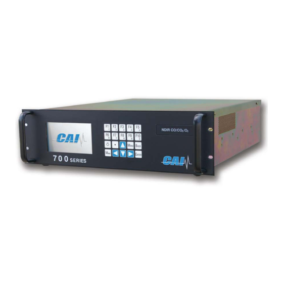
CAI 700 Series Operator's Manual (203 pages)
CLD NOx/O2
Brand:
CAI
| Category:
Measuring Instruments
| Size: 6 MB
Table of Contents
Table of Contents
2
Introduction
5
Operating Principle
6
Reaction Chamber
6
Flow System
7
Analyzer Specifications
8
Installation
10
Safety Information
10
Electrical Shock Hazard
11
Unpacking Instructions
13
Rack Mounting
14
Rear Panel
14
Site Selection and Mounting
15
Output Connections
16
Gas Handling Equipment
17
Gas Connections
17
Sampling Requirements
18
Startup and Shutdown
20
Shutdown Procedure
20
Proper Storage
21
Using the Keypad
22
Menu Flow Chart
24
Range Setup
26
Main Menu
32
Measure Screen
33
Measure Mode
36
NO Mode
37
X Mode
37
NO X /NO 2 Mode
38
Analyzer Info
39
Remote/Manual
40
Standby
41
Menus
42
Calibration
43
Manual Calibration
44
Or no X Mode
45
Zero
46
Span
49
NO X /NO 2 Mode
51
Automated Calibration
52
Initiate Sequenced Cal
54
Initiate Sequenced Check
56
Cal Gas Concentrations
57
Calibration Setup
58
Auto Calibration Schedule
59
Auto Calibration Parameters
61
Calibration Via Pump/Valves
63
Auto Calibration/Check
64
Auto Calibration Timing
65
Deviation Limits
67
Maximum Calibration Error
68
Maximum Verifying Error
69
Analog Hold on Cal
70
Calibration Factors
71
Manual Deviations
72
Zero Gas Deviations
73
Span Gas Deviations
74
Auto Cal Deviations
75
Verifying Zero Deviations
76
Verifying Span Deviations
77
Offset/Gain Factors
78
Reset Factory Settings
79
Range Setup
82
Range Limits
83
Auto Range On/Off
85
Autorange Switch Points
86
Diagnostics
87
Diagnostic Values
88
Raw Values Display
90
I/O Status
92
Analyzer Digital Outputs
93
Analyzer Digital Inputs
94
Programmable Digital Outputs
95
Status Line
96
Setup Menu
97
Measure Settings
98
Averaging Time
99
NO X /NO 2 Mode Times
100
Nox Correction Factors
101
Output Settings
103
Programmable Analogs
104
Output Assignments
105
Output Scaling
107
Output Adjustments
109
Programmable Digitals
111
Output Assignments
112
Output Hold/Clear
115
Output Test
116
TCP/IP Parameters
118
Data Logging Time
119
Auto Start Settings
120
Clock Settings
122
Alarms Menu
123
Current Alarms
124
Alarm Log
125
Alarm Limits
127
Temperatures
128
Pressures
129
EPC Voltages
130
Concentrations
131
Alarm Display On/Off
132
Service Menu
133
Linear Coefficients
134
Service Menu
136
Security
137
Operator Levels
138
Change Password
139
Reset Password
140
Communication and Interface
141
Analog and Digital Interface
142
Serial Interface
146
AK Protocol
147
Instruction Command
149
Acknowledgement Command
150
Error Handling
151
General AK Requirements
152
Scan Commands
154
AKON: Measured Concentration Value
159
AMBE: Measuring Range Limit
159
AMBU: Upper and Lower Range Switchover Values for Auto Range
159
ASTF: Error Status
161
Control Commands
165
Configuration Commands
169
Modbus Protocol
175
MBAP Description
175
MBAP Header Description
176
Modbus Command Function Codes
177
Modbus Map
194
01H Single-Read Coil
194
05H Write Single Coil
196
03H Read Floating Point
197
16H Write Floating Point
200
Warranty Statement
202
Advertisement
CAI 700 Series Operator's Manual (205 pages)
MHFID THC/CH4
Brand:
CAI
| Category:
Measuring Instruments
| Size: 7 MB
Table of Contents
Table of Contents
2
Introduction
5
Analyzer Specifications
9
Installation
11
Safety Information
11
Startup and Shutdown
22
Using the Keypad
24
Menu Flow Chart
26
Main Menu
34
Measure Screen
35
Measure Mode
38
THC Mode
39
CH 4 Mode
39
Thc/Ch
40
Analyzer Info
41
Remote/Manual
42
Standby
43
Ignition
44
Menus
45
Calibration
46
Manual Calibration
47
THC or CH Mode
48
Zero
49
Span
52
Thc/Ch
54
Automated Calibration
55
Initiate Sequenced Cal
57
Initiate Sequenced Check
59
Cal Gas Concentrations
60
Calibration Setup
61
Auto Calibration Schedule
62
Auto Calibration Parameters
64
Calibration Via Pump/Valves
66
Auto Calibration/Check
67
Auto Calibration Timing
68
Deviation Limits
70
Maximum Calibration Error
71
Maximum Verifying Error
72
Analog Hold on Cal
73
Calibration Factors
74
Manual Deviations
75
Zero Gas Deviations
76
Span Gas Deviations
77
Auto Cal Deviations
78
Verifying Zero Deviations
79
Verifying Span Deviations
80
Offset/Gain Factors
81
Reset Factory Settings
82
Range Setup
85
Range Limits
86
Autorange On/Off
88
Autorange Switch Points
89
Diagnostics
90
Diagnostic Values
91
Raw Values Display
93
I/O Status
95
Analyzer Digital Outputs
96
Analyzer Digital Inputs
97
Programmable Digital Outputs
98
Status Line
99
Setup Menu
100
Measure Settings
101
Averaging Time
102
THC/CH /NMHC Mode Times
103
CH 4 Correction Factors
104
Output Settings
106
Programmable Analogs
107
Output Assignments
108
Output Scaling
110
Output Adjustments
112
Programmable Digitals
114
Output Assignments
115
Output Hold/Clear
118
Output Test
119
TCP/IP Parameters
121
Data Logging Time
122
Auto Start Settings
123
Clock Settings
125
Alarms Menu
126
Current Alarms
127
Alarm Log
128
Alarm Limits
130
Temperatures
131
Pressures
132
EPC Voltages
133
Concentrations
134
Alarm Display On/Off
135
Service Menu
136
Linear Coefficients
137
Factory Service
139
Security
140
Operator Levels
141
Change Password
142
Reset Password
143
Communication and Interface
144
Analog and Digital Interface
145
Serial Interface
149
AK Protocol
150
Instruction Command
152
Error Handling
154
General AK Requirements
155
Scan Commands
157
Control Commands
168
Configuration Commands
172
Modbus Protocol
177
MBAP Description
177
MBAP Header Description
178
Modbus Command Function Codes
179
Modbus Map
196
1 H Single-Read Coil
196
05H Write Single Coil
198
3 H Read Floating Point
199
16H Write Floating Point
202
Warranty Statement
204
CAI 700 Series Operator's Manual (205 pages)
Brand:
CAI
| Category:
Measuring Instruments
| Size: 6 MB
Table of Contents
Table of Contents
2
Introduction
5
Operating Principle
7
Analyzer Specifications
8
Installation
9
Safety Information
9
Startup and Shutdown
19
Using the Keypad
21
Menu Flow Chart
23
Main Menu
31
Measure Screen
33
Change Channel
36
Analyzer Info
37
Remote/Manual
38
Standby
39
Menus
40
Calibration
41
Manual Calibration
42
Zero
43
Span
46
Automated Calibration
48
Initiate Sequenced Cal
50
Initiate Sequenced Check
52
Cal Gas Concentrations
53
Calibration Setup
54
Auto Calibration Schedule
54
Auto Calibration Parameters
57
Calibration Via Pump/Valves
59
Auto Calibration/Check
60
Auto Calibration Timing
61
Deviation Limits
63
Maximum Calibration Error
64
Maximum Verifying Error
65
Analog Hold on Cal
66
Calibration Factors
67
Manual Deviations
68
Zero Gas Deviations
69
Span Gas Deviations
70
Auto Cal Deviations
71
Zero Gas Deviations Verifying
72
Span Gas Deviations Verifying
73
Offset/Gain Factors
74
Reset Factory Settings
75
Range Setup
80
Range Limits
81
Auto Range On/Off
83
Autorange Switch Points
84
Diagnostics
85
Diagnostic Values
86
Raw Values Display
89
I/O Status
91
Analyzer Digital Outputs
92
Analyzer Digital Inputs
93
Programmable Digital Outputs
94
Status Line
95
Setup Menu
96
Measure Settings
97
Averaging Time
98
Comp Factors
99
T & P Compensation
100
H2O Compensation
100
Gas Compensation
101
Output Settings
102
Programmable Analogs
103
Output Assignments
104
Output Scaling
106
Output Adjustments
108
Programmable Digitals
110
Output Assignments
111
Output Hold/Clear
114
TCP/IP Parameters
117
Data Logging Time
118
Auto Start Settings
119
Clock Settings
121
Alarms Menu
122
Current Alarms
123
Alarm Log
124
Alarm Limits
126
Temperatures
127
Pressures
128
Voltages
129
Concentrations
130
Alarm Display On/Off
131
Service Menu
132
Linear Coefficients
133
Factory Service
135
Security
136
Operator Levels
137
Change Password
138
Reset Password
139
Communication and Interface
140
Analog and Digital Interface
141
Serial Interface
145
AK Protocol
146
Instruction Command
148
Acknowledgement Command
149
Error Handling
150
General AK Requirements
151
Scan Commands
153
Control Commands
164
Configuration Commands
168
Modbus Protocol
174
MBAP Description
174
MBAP Header Description
175
Modbus Command Function Codes
176
Modbus Map
193
1 H Single-Read Coil
193
3 H Read Floating Point
197
16H Write Floating Point
202
Warranty Statement
204
Advertisement
Advertisement
Related Products
CAI 700 NDIR
CAI 700 CLD Series
CAI 750 CLD
CAI 700 HCLD NOX Series
CAI 700M
CAI 700 LX Series
CAI 750
CAI 600 Series
CAI 600-NDIR
CAI Categories
Measuring Instruments
Stereo System
Indoor Furnishing
Analytical Instruments
Ladders
More CAI Manuals
Login
Sign In
OR
Sign in with Facebook
Sign in with Google
Upload manual
Upload from disk
Upload from URL