Sign In
Upload
Manuals
Brands
BECKWITH ELECTRIC Manuals
Protection Device
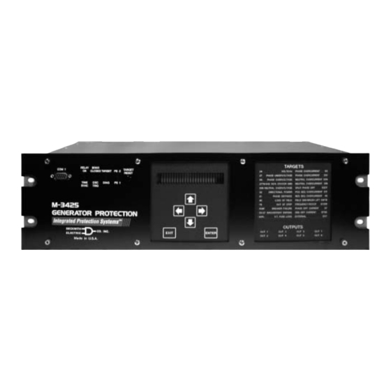
M-3425
BECKWITH ELECTRIC M-3425 Manuals
Manuals and User Guides for BECKWITH ELECTRIC M-3425. We have
1
BECKWITH ELECTRIC M-3425 manual available for free PDF download: Instruction Book
BECKWITH ELECTRIC M-3425 Instruction Book (225 pages)
Generator Protection
Brand:
BECKWITH ELECTRIC
| Category:
Protection Device
| Size: 2 MB
Table of Contents
Table of Contents
24
M-3425 Generator Protection
34
Instruction Book Contents
34
Chapter 1 Introduction
34
M-3425 Generator Protection Relay
35
Appendix A: Configuration Record Forms
35
Accessories
37
M-3925 Target Module
37
M-3931 Human-Machine Interface (HMI) Module
37
Chapter 2 Application
38
Configuration
38
Functions
38
Relay System Setup
40
System Diagrams
42
Setpoints and Time Settings
45
Phase Distance
46
Phase Distance (21) Function Applied for System Backup
47
Phase Distance (21) Coverage
48
Volts/Hz
49
RMS Undervoltage, 3-Phase
52
RMS Undervoltage, 3 Phase
52
27TN Third Harmonic Undervoltage, Neutral Circuit
53
Directional Power, 3-Phase
55
Directional Power, 3 Phase
55
Tripping on Low Forward Power in Positive Direction (Toward System)
55
Loss of Field
57
Negative Sequence Overcurrent
60
Negative Sequence Overcurrent Inverse Time Curves
61
50/50N Instantaneous Overcurrent, Phase and Neutral Circuits
62
50BF Generator Breaker Failure/50N HV Breaker Flashover
63
Breaker Failure Logic Diagram
63
50DT Definite Time Overcurrent (for Split-Phase Differential)
65
50DT Definite Time Overcurrent for Split-Phase Differential
65
Inverse Time Neutral Overcurrent
66
Inverse Time Positive Sequence Overcurrent for
67
Inverse Time Positive Sequence Overcurrent (51T) Setpoint Ranges
67
Inverse Time Curve - 51T
68
Inverse Time Phase Overcurrent with Voltage Control/Restraint
69
Voltage Restraint (51VR) Characteristic
70
Delta/Wye Transformer Voltage-Current Pairs
70
50/27 Inadvertant Energizing
71
Inadvertent Energizing (50/27) Setpoint Ranges
71
Inadvertent Energizing Function Logic Diagram
72
RMS Overvoltage, 3-Phase
73
RMS Overvoltage, 3 Phase
73
RMS Overvoltage, 3-Phase (59) Setpoint Ranges
73
RMS Overvoltage, Neutral Circuit or Zero Sequence
74
RMS Overvoltage, Neutral Circuit or Zero Sequence (59N) Setpoint Ranges
74
60FL Fuse Loss
75
Brush Lift-Off Detection
76
Brush Lift-Off Detection (64B) Setpoint Ranges
77
Field Ground Protection
78
M-3921 Field Ground Coupler
78
Field Ground Protection (64F) Setpoint Ranges
78
Out of Step
80
Frequency
82
Rate of Change of Frequency
84
Rate of Change of Frequency (81R) Setpoint Ranges
84
87GD Ground (Zero Sequence) Differential
85
Ground Differential (87GD) Setpoint Ranges
85
Phase Differential
86
Differential Relay (87) Operating Characteristics
86
External Functions
87
External Functions Setpoint Range
87
External Function Example
88
Chapter 3 Operation
90
Front Panel Controls
90
Initial Setup Procedure/Settings
92
Setup Unit Data
92
Setup System Data
95
Configure Relay Data
95
Setpoint and Time Settings
96
Oscillograph Recorder Data
96
Communications Data
96
Status/Metering
97
Monitor Status/Metering
97
Target History
98
Chapter 4 Remote Operation
100
Direct Connection
100
Multiple Systems Setup
101
Serial Multidrop Network Setup
101
Setting up the M-3425 Generator Protection Relay for Communications
102
Installing the Modems
102
Dead Sync Time
102
Installation and Setup (Ipscom)
103
Hardware Requirements
104
Installation
104
Installing Ipscom
104
Installing Ipsutil
104
Operation
104
Activating Communications
104
Overview
106
File Menu
106
Comm Menu
107
Relay Menu
108
Window Menu/Help Menu
114
Checkout Status/Metering
115
Checkout Status/Metering (Windows)
115
Cautions
118
Keyboard Shortcuts
119
Ipsutil™ Communications Software
120
Chapter 5 Installation
126
General Information
126
Mechanical/Physical Dimensions
126
Three-Line Connection Diagram
126
Commissioning Checkout
133
Circuit Board Switches and Jumpers
136
Chapter 6 Testing
139
Equipment/Test Setup
139
Auto-Calibration
139
Diagnostic Test Procedures
143
Output Test
143
Output Contacts
143
Input Test
144
Input Contacts
144
Status LED Test
145
Target LED Test
145
Button Test
146
Display Test
146
COM1/COM2/COM3 Loopback Test
146
COM3 Test (2-Wire)
147
Clock Test
148
Flash Relay OK LED Test
148
Auto Calibration
148
Factory Use Only
148
Phase and Neutral Calibration
148
Third Harmonic Calibration
149
Field Ground Calibration
149
Functional Test Procedures
152
Power on Selftests
153
Phase Distance
154
RMS Undervoltage, 3-Phase
158
27TN Third-Harmonic Undervoltage, Neutral
159
Loss of Field
162
Negative Sequence Overcurrent Definite Time
163
Negative Sequence Overcurrent Inverse Time
164
Instantaneous Phase Overcurrent
165
50BF Breaker Failure
166
50BF/50BF-N Breaker Failure
166
50/27 Inadvertent Energizing
168
50DT Definite Time Overcurrent for Split-Phase Differential
169
Instantaneous Neutral Overcurrent
170
Inverse Time Neutral Overcurrent
171
Inverse Time Positive Sequence Overcurrent for Stator Thermal Protection
172
Inverse Time Phase Overcurrent with Voltage Control/Restraint
173
RMS Overvoltage, 3-Phase
174
RMS Overvoltage, Neutral Circuit or Zero Sequence
175
60FL VT Fuse Loss Detection
176
Field Ground Protection
177
Brush Lift off Detection
179
Out of Step
180
Frequency
181
Rate of Change of Frequency
182
Phase Differential
184
87GD Ground Differential
185
EXT External Functions
186
Relay Configuration Table
189
Appendix B-Communications
200
Appendix C-Self-Test Error Codes
204
Appendix D: Inverse Time Curves
208
Advertisement
Advertisement
Related Products
BECKWITH ELECTRIC M-3425A
BECKWITH ELECTRIC M-0329B
BECKWITH ELECTRIC M?3311A
BECKWITH ELECTRIC Syncrocloser M-3410A
BECKWITH ELECTRIC M-3520
BECKWITH ELECTRIC BlueJay M-2911
BECKWITH ELECTRIC M-0290
BECKWITH ELECTRIC M-0420
BECKWITH ELECTRIC Syncrocloser M-5625
BECKWITH ELECTRIC M-0236B
BECKWITH ELECTRIC Categories
Relays
Controller
Transceiver
Protection Device
Control Systems
More BECKWITH ELECTRIC Manuals
Login
Sign In
OR
Sign in with Facebook
Sign in with Google
Upload manual
Upload from disk
Upload from URL