Sign In
Upload
Manuals
Brands
BECKWITH ELECTRIC Manuals
Relays
M-3520
BECKWITH ELECTRIC M-3520 Manuals
Manuals and User Guides for BECKWITH ELECTRIC M-3520. We have
1
BECKWITH ELECTRIC M-3520 manual available for free PDF download: Instruction Book
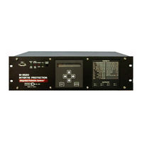
BECKWITH ELECTRIC M-3520 Instruction Book (217 pages)
Intertie Protection Relay
Brand:
BECKWITH ELECTRIC
| Category:
Relays
| Size: 2 MB
Table of Contents
Table of Contents
20
Chapter 1 Introduction
30
Instruction Book Contents
30
M-3520 Intertie Protection
31
Accessories
33
Chapter 2 Application
34
Introduction
34
System Diagrams
35
Configuration
37
Functions
37
Special Input/Output Considerations
37
System Setup
38
Setpoints and Time Settings
40
Phase Distance
40
Sync Check
48
Undervoltage, 3-Phase
49
Directional Power
50
Negative Sequence Overcurrent
54
Negative Sequence Overvoltage
55
Instantaneous Overcurrent, 3-Phase
56
Instantaneous Overcurrent, Neutral
57
Inverse Time Overcurrent with Voltage Control or Voltage Restraint
58
Inverse Time Neutral Overcurrent
61
Peak Overvoltage
62
Overvoltage, 3-Phase
63
27G Overvoltage/Undervoltage, Neutral Circuit or Zero Sequence
64
60FL Fuse Loss
68
Phase Directional Overcurrent
71
Residual Directional Overcurrent
72
Out of Step
74
Reconnect Enable Time Delay
76
Frequency
79
Rate of Change of Frequency
80
Oscillograph Recorder
81
Target History Recorder
82
Chapter 3 Operation (Front Panel)
84
Front Panel Controls
84
Alphanumeric Display
84
Arrow Buttons
85
Exit Button
85
Enter Button
85
Target/Status Indicators and Control
85
Power Supply (PS1 and PS2)
85
Relay OK LED
85
Oscillograph (OSC TRIG) LED
85
Breaker (BRKR) Closed LED
85
Time Sync LED
85
Diagnostic LED (DIAG LED)
85
Default Message Screens
86
Serial Interfaces (COM1, COM2 and COM3)
86
Communication Specifications
86
Initial Setup Procedure/Settings
89
Setup Procedure
89
Communication Data
91
Setup Unit Data
91
Setup System
91
Configure Relay Data
91
Setpoints and Time Settings
93
Oscillograph Recorder Data
93
Target History Recorder
93
Checkout Status/Metering
94
Chapter 4 Operation (Computer)
96
Installation and Setup
96
Hardware Requirements
96
Use of Ipscom
97
Using a Modem
97
Use of Ipscom and M-3520 Intertie Protection Relay Using Direct Serial Connection
97
Installation
97
Installing Ipscom
97
Installing Ipsutil
97
Installing the Modems
97
Setting up the M-3520 Intertie Protection Relay for Communication
98
Multiple Systems Setup
99
Serial Multidrop Network Setup
99
Operation
100
Activating Communications
100
Overview
102
File Menu
102
Comm Menu
102
Relay Menu
104
Window Menu
109
Help Menu
109
Cautions
110
Checkout Status/Metering
111
Keyboard Shortcuts
115
Ipsutil™ Communications Software
116
M-3890 Ipsutil
117
Installation and Setup
117
Hardware Requirements
117
Installation
117
System Setup
117
Overview
117
Comm Menu
117
Relay Comm
118
Clock
119
Security Menu
119
Miscellaneous Menu
120
Help Menu
121
Chapter 5 Installation
122
General Information
122
Mechanical/Physical Dimensions
122
External Connections
127
Commissioning Checkout
129
Circuit Board Switches and Jumpers
131
Equipment and Test Setup
135
Diagnostic Test Procedures
136
Output Test (Relay)
137
Input Test (Status)
138
Status LED Test
138
Target LED Test
139
Expanded I/O Test
139
Button Test
139
Display Test
140
COM3 Test (2Wire)
140
COM3 Test (4Wire)
141
Clock Test
141
Flash Relay OK LED
142
Factory Use Only
142
Chapter 6 Testing
142
Automatic Calibration
143
Input Configurations
144
Functional Test Procedures
145
Phase Distance (#1, #2)
146
Sync Check
148
Undervoltage, 3 Phase (#1, #2)
150
Undervoltage, 3 Phase
150
Undervoltage, Neutral
151
Directional Power, #1 or #2
152
46DT Negative Sequence Overcurrent Definite Time
154
46IT Negative Sequence Overcurrent Inverse Time
155
Negative Sequence Overvoltage
156
Instantaneous Phase Overcurrent
157
Instantaneous Phase Overcurrent, Neutral
158
Inverse Time Overcurrent, Phase
159
Inverse Time Residual Overcurrent, Neutral
160
Overvoltage, 3-Phase (#1 or #2)
161
Peak Overvoltage, 3-Phase
162
Neutral Overvoltage
163
67DT Definite Time Directional Overcurrent
165
Out of Step
171
Reconnect
172
Frequency (#1, #2, #3, or #4)
173
Rate of Change of Frequency (#1, #2)
174
Appendix A: Configuration Record Forms
176
Appendix B: Communications
196
Appendix C: Error Codes
200
Appendix D: Inverse Time Curves
202
Appendix E: Layup and Storage
214
Advertisement
Advertisement
Related Products
BECKWITH ELECTRIC M-0127A
BECKWITH ELECTRIC M-0170A
BECKWITH ELECTRIC M-0245C
BECKWITH ELECTRIC M-0420
BECKWITH ELECTRIC M?3311A
BECKWITH ELECTRIC Syncroclosure M-0193B
BECKWITH ELECTRIC M-0236B
BECKWITH ELECTRIC SYNCROCLOSER M-0188A
BECKWITH ELECTRIC M-3425A
BECKWITH ELECTRIC Syncrocloser M-3410A
BECKWITH ELECTRIC Categories
Relays
Controller
Transceiver
Protection Device
Control Systems
More BECKWITH ELECTRIC Manuals
Login
Sign In
OR
Sign in with Facebook
Sign in with Google
Upload manual
Upload from disk
Upload from URL