Atmel AVR AT90CAN32 Manuals
Manuals and User Guides for Atmel AVR AT90CAN32. We have 2 Atmel AVR AT90CAN32 manuals available for free PDF download: Manual
Atmel AVR AT90CAN32 Manual (429 pages)
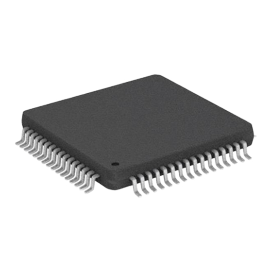
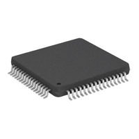
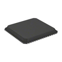
8-bit Microcontroller with 32K/64K/128K Bytes of ISP Flash and CAN Controller
Brand: Atmel
|
Category: Microcontrollers
|
Size: 4 MB
Table of Contents
Advertisement
Atmel AVR AT90CAN32 Manual (17 pages)
8-bit Microcontroller with 32K/64K/128K Bytes of ISP Flash and CAN Controller
Brand: Atmel
|
Category: Microcontrollers
|
Size: 0 MB