Sign In
Upload
Manuals
Brands
Artesyn Manuals
Motherboard
MVME8105
Artesyn MVME8105 Manuals
Manuals and User Guides for Artesyn MVME8105. We have
3
Artesyn MVME8105 manuals available for free PDF download: Manual, Installation And Use Manual, Programmer's Reference Manual
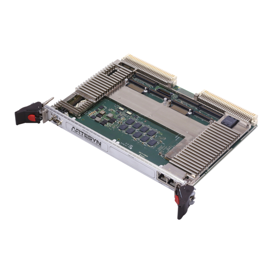
Artesyn MVME8105 Installation And Use Manual (120 pages)
Brand:
Artesyn
| Category:
Motherboard
| Size: 1 MB
Table of Contents
Table of Contents
3
About this Manual
11
Safety Notes
17
Sicherheitshinweise
21
1 Introduction
27
Overview
27
Feature Summary
28
Table 1-1 Board Feature Summary
28
Table
29
Ordering and Support Information
31
Standard Compliances
32
Mechanical Data
32
Table 1-2 Board Standard Compliances
32
Mechanical Data
33
2 Hardware Preparation and Installation
35
Overview
35
Unpacking and Inspecting the Board
36
Requirements
37
Environmental Requirements
37
Table 2-1 MVME8100/MVME8105/MVME8110 Specifications
37
Power Requirements
39
Table 2-2 Operating Voltages
39
Table 2-3 Power Requirements
39
Thermal Requirements
40
Thermally Significant Components
40
Equipment Requirements
40
Configuring the Board
41
Figure 2-1 Switch Locations (ENP1 Board)
41
Figure 2-2 Switch Locations (ENP4 Board)
42
Installing Accessories
43
Rear Transition Module
43
PMC/XMC Installation
44
Figure 2-3 Typical Placement of a PMC/XMC Module on a VME Module
46
SATA Installation
47
Figure 2-4 SATA Drive Installation
48
Figure
48
Installing and Removing the Board
49
Completing the Installation
51
3 Connectors, Leds, and Switches
53
Overview
53
Front Panel
53
Figure 3-1 MVME8100 - ENP1 Board Connectors, Leds, Switches
53
Figure 3-2 MVME8100 - ENP4 Leds and Switches
54
Figure 3-3 MVME8105 - ENP1 Board Connectors, Leds, Switches
55
Connectors
56
External Connectors
56
Front Panel Connectors
56
Table 3-1 Console Front Panel Connector (J1)
56
Table 3-2 Front Panel Tri-Speed Ethernet Connector (J4)
57
Backplane Connectors
58
Table 3-4 P1 Connectors and Signal Descriptions
58
Table 3-5 P2 Connectors and Signal Descriptions
60
On-Board Connectors
63
Table 3-6 VXS P0 Connector (Applicable to MVME8100 Only)
63
Table 3-7 Customized SATA Connector (J3)
64
Table 3-8 PMC J11/J21 Connector and Signal Description
65
Table 3-9 PMC J12/J22 Connector and Signal Descriptions
66
Table 3-10 PMC J13/J23 Connectors and Signal Descriptions
68
Table 3-11 PMC J14 Connectors and Signal Descriptions
70
Table 3-12 Asset JTAG Header Pin Assignment (P12)
71
Table 3-13 XMC Connectors and Signal Descriptions
72
Leds
74
On-Board Leds
75
Switches
75
Table 3-15 On-Board Leds Status
75
Configuration Switches
76
S2 Switch
76
S3 Switch
77
Table 3-18 Three Row Backplane Manual Slot Addressing
77
S4 Switch
79
S5 Switch
79
Reset /Abort Switch
80
4 Functional Description
81
Overview
81
Block Diagrams
81
Figure 4-1 Block Diagram of MVME8100
81
Figure 4-2 Block Diagram of MVME8105
82
Figure 4-3 Block Diagram of MVME8110
83
Processor
84
System Memory
84
Timers
85
Real Time Clock
85
P5020/P5010 Internal Timers
85
Watchdog Timers
85
Initial Hardware Watchdog
86
OS Watchdog
86
CPLD Tick Timer
86
Ethernet Interfaces
87
SPI Interface
87
SPI Flash Memory
87
Firmware Redundancy
88
Mram
88
Emmc
88
Processor Console Port
88
Rear UART Ports
89
Pcie Ports
89
SRIO Ports
90
Pcie Ports
90
PMC/XMC Sites
91
Figure 4-5 SRIO Bus Topology
91
PMC Add-On Card
92
XMC Add-On Card
93
SATA Interface
93
VME Support
93
Tsi148 VME Controller
93
Tsi384 Pcie to PCI/PCI-X Bridge
94
Usb
94
I2C Devices
94
Reset/Control CPLD
95
Power Management
96
Power Distribution Structure
97
Power Sequence Requirements
97
Figure 4-7 Power Distribution
97
Clock Structure
98
Figure
98
Reset Structure
99
Figure 4-9 Reset Control Diagram
99
Interrupt Controller Assignments
100
Table 4-1 P5020 / P5010 External Interrupt Assignments
100
GPIO Electrical Characteristics
101
Thermal Management
101
Table 4-2 GPIO DC Electrical Characteristics
101
Table 4-3 GPIO Pull-Down Characteristics
101
Figure 4-10 Thermal Management
102
5 Boot System
103
Overview
103
Accessing U-Boot
103
Boot Options
104
Booting from a Network
104
Booting from an Optional SATA Drive
105
Booting from a USB Drive
105
Booting from Emmc
106
Booting Vxworks through the Network
107
MVME8100/MVME8105/MVME8110 Specific U-Boot Commands
107
Table 5-1 Mvme8100/Mvme8105/Mvme8110Specific U-Boot Commands
107
Updating U-Boot
111
Battery Exchange
113
Figure A-1 Battery Location
113
A.1 Battery Exchange
113
Related Documentation
115
Artesyn Embedded Technologies Documentation
115
Table B-1 Artesyn Embedded Technologies - Embedded Computing Publications
115
Related Specifications
116
Table B-2 Related Specifications
116
Manufacturers' Documents
117
Table B-3 Manufacturer's Publications
117
B.3 Manufacturers' Documents
117
Advertisement
Artesyn MVME8105 Manual (124 pages)
Brand:
Artesyn
| Category:
Motherboard
| Size: 1 MB
Table of Contents
Table of Contents
3
About this Manual
11
Safety Notes
17
Sicherheitshinweise
21
Introduction
27
Features
27
Standard Compliances
37
Mechanical Data
37
Table 1-1 Board Standard Compliances
37
Ordering Information
38
Supported Board Models
38
Mechanical Data
38
Board Variants
38
Board Accessories
39
Hardware Preparation and Installation
41
Unpacking and Inspecting the Board
42
Requirements
43
Environmental Requirements
43
Table 2-1 MVME8100/MVME8105/MVME8110 Specifications
43
Power Requirements
45
Table 2-2 Operating Voltages
45
Table 2-3 Power Requirements
45
Thermal Requirements
46
Thermally Significant Components
46
Equipment Requirements
46
Configuring the Board
46
Installing Accessories
47
Figure 2-1 Switch Locations (ENP1 Board)
47
Figure 2-2 Switch Locations (ENP4 Board)
47
Rear Transition Module
48
PMC/XMC Installation
49
SATA Installation
52
Figure 2-3 Typical Placement of a PMC/XMC Module on a VME Module
52
Figure 2-4 SATA Drive Installation
54
Installing and Removing the Board
55
Completing the Installation
57
Connectors, Leds, and Switches
59
Figure 3-1 ENP1 Board Connectors, Leds, Switches
59
Figure 3-2 ENP4 Leds and Switches
60
Figure 3-3 ENP1 Board Connectors, Leds, Switches
61
Connectors
62
External Connectors
62
Front Panel Connectors
62
Table 3-1 Console Front Panel Connector (J1)
62
Table 3-2 Front Panel Tri- Speed Ethernet Connector (J4)
62
Backplane Connectors
64
P1 Connectors
64
Table
65
P2 Connectors
66
Table
67
Table
68
Table 3-6 VXS P0 Connector (Applicable to MVME8100 Only)
68
On-Board Connectors
69
Table 3-7 Customized SATA Connector (J3)
69
Table
70
Table 3-8 PMC J11/J21 Connector
70
Table 3-9 PMC J12/J22 Connector
72
Table
73
Table 3-10 PMC J13/J23 Connectors
73
Table
74
Table
75
Table 3-12 Asset JTAG Header Pin Assignment (P12)
76
Table
76
XMC Connectors
77
Leds
78
On-Board Leds
79
Switches
79
Table 3-15 On-Board Leds Status
79
Configuration Switches
80
S2 Switch
80
S3 Switch
81
Table 3-18 Three Row Backplane Manual Slot Addressing
82
S4 Switch
83
S5 Switch
83
Reset /Abort Switch
84
Functional Description
85
Block Diagram
86
Figure 4-1 Block Diagram of MVME8100
86
Figure 4-2 Block Diagram of MVME8110
87
Figure 4-3 Block Diagram of MVME8105
88
Processor
89
System Memory
89
Timers
89
Real Time Clock
90
P5020/ P5010 Internal Timers
90
Watchdog Timers
90
Initial Hardware Watchdog
91
OS Watchdog
91
CPLD Tick Timer
91
Ethernet Interfaces
91
SPI Interface
92
SPI Flash Memory
92
Firmware Redundancy
92
Mram
93
Emmc
93
Processor Console Port
93
Rear UART Ports
94
Pcie Ports
94
SRIO Ports
95
Figure 4-5 SRIO Bus Topology
96
PMC/XMC Sites
97
PMC Add-On Card
97
XMC Add-On Card
98
SATA Interface
98
VME Support
98
Tsi148 VME Controller
99
Tsi384 Pcie to PCI/PCI-X Bridge
99
Usb
99
I2C Devices
99
Reset/Control CPLD
100
Power Management
101
Power Distribution Structure
102
Power Sequence Requirements
102
Figure 4-7 Power Distribution
102
Clock Structure
103
Figure 4-8 Clock Structure
103
Reset Structure
104
Figure 4-9 Reset Control Diagram
105
Interrupt Controller Assignments
106
Table 4-1 P5020 / P5010 External Interrupt Assignments
106
GPIO Electrical Characteristics
107
Thermal Management
107
Table 4-2 GPIO DC Electrical Characteristics
107
Table 4-3 GPIO Pull-Down Characteristics
107
Figure 4-10 Thermal Management
108
Boot System
109
Accessing U-Boot
109
Boot Options
110
Booting from a Network
110
Booting from an Optional SATA Drive
111
Booting from a USB Drive
111
Booting from Emmc
112
Booting Vxworks through the Network
112
MVME8100/MVME8105/MVME8110 Specific U-Boot Commands
113
Table 5-1 Mvme8100/Mvme8105/Mvme8110Specific U-Boot Commands
113
Updating U-Boot
115
Battery Exchange
117
Figure A-1 Battery Location
117
Table B-1 Artesyn Embedded Technologies - Embedded Computing Publications
119
Table B-2 Related Specifications
119
Table B-3 Manufacturer's Publications
121
Artesyn MVME8105 Programmer's Reference Manual (52 pages)
Brand:
Artesyn
| Category:
Motherboard
| Size: 0 MB
Table of Contents
Table of Contents
3
About this Manual
9
Summary of Changes
12
1 Introduction
13
Overview
13
Feature Summary
14
Table 1-1 Board Feature Summary
14
Table
15
Table
16
Ordering and Support Information
17
Block Diagram
18
Figure 1-3 Block Diagram of MVME8110
20
2 Memory Maps
21
Overview
21
Table 2-1 P5010/P5020 Local Memory Mapping (36-Bit Physical Memory Map)
21
3 Register Descriptions
23
Overview
23
CPLD Registers
23
Table 3-2 Register Access Type
23
Enhanced Local Bus Register
24
Table 3-3 Enhanced Local Bus Register Overview
24
Identification Register
25
Table 3-4 Identification Register
25
CPLD Command/Status Register
26
Table 3-5 CPLD Command/Status Register
26
Table 3-6 User LED Control Register
30
User LED Control Register
30
CPLD Build Code Register
31
Table 3-7 CPLD Build Code Register
31
Table 3-8 Tick Timer Control Register
32
Tick Timer Register
32
Table 3-10 Tick Timer Prescaler Register
33
Table 3-9 Tick Timer Compare Register
33
RTM GPIO Register
34
Scratch Register
34
Table 3-11 Tick Timer Counter Register
34
4 Programming Model
35
Overview
35
Interrupt Controller Assignments
35
Table 4-1 P5020 External Interrupt Assignments
35
Ethernet PHY Management Addresses
36
Local Bus Controller Chip Select Assignment
36
Gbe PHY Address
36
Table 4-3 LBC Chip Select Assignment
36
I 2 C Devices
37
Table 4-4 I 2 C Busses and Devices
37
5 Boot System
39
Overview
39
Accessing U-Boot
39
Boot Options
40
Booting from a Network
40
Booting from an Optional SATA Drive
41
Booting from a USB Drive
41
Booting from MMC
42
Booting Vxworks through the Network
42
MVME8100/MVME8105/MVME8110 Specific U-Boot Commands
43
Table 5-1 MVME8100/MVME8105/MVME8110 Specific U-Boot Commands
43
Updating U-Boot
46
Related Documentation
47
Artesyn Embedded Technologies Documentation
47
Table A-1 Artesyn Embedded Technologies Publications
47
Related Specifications
48
Table A-2 Related Specifications
48
Manufacturers' Documents
49
Table A-3 Manufacturer's Publications
49
A.3 Manufacturers' Documents
49
Advertisement
Advertisement
Related Products
Artesyn MVME8100
Artesyn MVME8110
Artesyn MVME4100
Artesyn MVME55006E
Artesyn MVME6100
Artesyn MVME2500-0173
Artesyn MVME2500-02120201E
Artesyn MVME2500-0161
Artesyn MVME2500ET-0171
Artesyn MVME2500ET-0173
Artesyn Categories
Motherboard
Server
Single board computers
PCI Card
Computer Hardware
More Artesyn Manuals
Login
Sign In
OR
Sign in with Facebook
Sign in with Google
Upload manual
Upload from disk
Upload from URL