Sign In
Upload
Manuals
Brands
Artesyn Manuals
Motherboard
MVME55006E
Artesyn MVME55006E Manuals
Manuals and User Guides for Artesyn MVME55006E. We have
1
Artesyn MVME55006E manual available for free PDF download: Installation And Use Manual
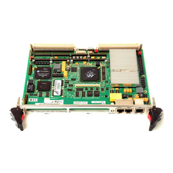
Artesyn MVME55006E Installation And Use Manual (142 pages)
P/N: 6806800A37J
Brand:
Artesyn
| Category:
Motherboard
| Size: 8 MB
Table of Contents
Table of Contents
3
List of Figures
12
About this Manual
13
Summary of Changes
17
1 Hardware Preparation and Installation
19
Overview
19
Introduction
19
Declaration of Conformity
20
Figure 1-1 Declaration of Conformity
20
Getting Started
21
Overview of Startup Procedures
21
Unpacking Guidelines
21
Configuring the Hardware
22
Configuring the Board
23
Table 1-2 MVME5500 Jumper Settings
23
Ethernet 2, PMC/SBC Mode, and P2 I/O Selection Headers (J6, J7, J28, J32, J34, J97 - J110)
26
Figure 1-2 MVME5500 Board Layout
26
Ethernet
27
PMC/SBC Mode Selection
27
P2 I/O Selection
28
Figure 1-3 Front Panel and Rear P2 Ethernet Settings
29
Flash Boot Bank Select Header (J8)
30
Figure 1-4 J28 and J32 Settings
30
Figure
30
J8 Settings
30
Flash 0 Programming Enable Switch (S3-1)
31
Safe Start ENV Switch (S5-1)
31
S3-1 Settings
31
S5-1 Settings
31
Flash 0 Block Write Protect Switch (S3-2)
32
SROM Initialization Enable Switch (S5-2)
32
S3-2 Settings
32
S5-2 Settings
32
PCI Bus 0.0 Speed Switch (S4-1)
33
VME SCON Select Header (J27)
33
S4-1 Settings
33
J27 Settings
33
PCI Bus 1.0 Speed Switch (S4-2)
34
EEPROM Write Protect Switch (S3-3)
34
S4-2 Settings
34
S3-3 Settings
34
1.7.12 Setting the PMC Vio Keying Pin
35
Installing the RAM5500 Module
35
Figure 1-15 VIO Keying Pin Settings
35
Installing Pmcs
37
Mounting the PMC Module
37
Primary Pmcspan
39
Figure 1-16 Typical Placement of a PMC Module on a VME Module
39
Figure 1-17 Pmcspan Installation on a VME Module
41
Secondary Pmcspan
42
1.10 Installing the Board
43
1.10.1 Connection to Peripherals
44
Figure 1-18 Installation into a Typical VME Chassis
44
1.10.2 Completing the Installation
45
1.11 Startup and Operation
45
Table 1-3 MVME5500 Connectors
45
1.12 Applying Power
46
1.13 Switches and Indicators
46
Table 1-4 Front-Panel LED Status Indicators
46
2 Functional Description
47
Overview
47
Block Diagram
47
Features
48
Table 2-1 MVME5500 Features Summary
48
Processor
49
L3 Cache
49
System Controller
50
CPU Bus Interface
50
Memory Controller Interface
50
Interrupt Controller
51
I2C Serial Interface and Devices
51
Direct Memory Access (DMA)
52
Timers
52
Flash Memory
53
System Memory
53
PCI Local Buses and Devices
53
Gigabit Ethernet Interface
53
10/100Mb Ethernet Interface
54
PCI-To-PCI Bridges
54
PMC Sites
54
PCI IDSEL Definition
54
PCI Bus Arbitration
55
2.10 Asynchronous Serial Ports
55
Figure 2-2 COM1 Asynchronous Serial Port Connections (RJ-45)
55
2.11 Real Time Clock and NVRAM
56
2.12 System Control and Status Registers
56
2.13 Sources of Reset
56
2.14 VME Interface
57
2.15 PMC Expansion
57
2.16 Debug Support
57
3 RAM55006E Memory Expansion Module
59
Overview
59
Features
59
Functional Description
59
RAM5500 Description
59
Table 3-1 RAM5500 Feature Summary
59
Srom
60
Figure 3-1 RAM500 Block Diagram
60
Clocks
61
Memory Expansion Connector Pin Assignments
61
Table 3-2 RAM5500 Connector (P1) Pin Assignments
61
RAM5500 Programming Issues
64
Serial Presence Detect (SPD) Data
64
4 Motload Firmware
65
Overview
65
Implementation and Memory Requirements
65
Motload Commands
65
Utilities
66
Tests
66
Command List
67
Table 4-1 Motload Commands
67
Using the Command Line Interface
72
Rules
74
Help
75
Firmware Settings
75
Default VME Settings
76
CR/CSR Settings
79
Displaying VME Settings
79
Editing VME Settings
80
Deleting VME Settings
80
Restoring Default VME Settings
81
Remote Start
81
5 Connector Pin Assignments
83
Introduction
83
Connectors
83
Asynchronous Serial Port Connector (J1)
84
Ethernet Connectors (J2)
84
Table 5-1 COM1 Connector (J1) Pin Assignments
84
Table 5-2 Ethernet Connector (J2) Pin Assignments
84
IPMC Connector (J3)
85
Table 5-3 IPMC Connector (J3) Pin Assignments
85
PCI/PMC Expansion Connector (J4)
87
Table 5-4 PCI/PMC Expansion Connector (J4) Pin Assignments
87
CPU COP Connector (J5)
89
Table 5-5 CPU COP Connector (J5) Pin Assignments
89
PMC 1 Interface Connectors (J11, J12, J13, J14)
90
Table 5-6 PMC 1 Connector (J11) Pin Assignments
90
Table 5-7 PMC 1 Connector (J12) Pin Assignments
91
Table 5-8 PMC 1 Connector (J13) Pin Assignments
93
Table 5-9 PMC 1 Connector (J14) Pin Assignments
94
Boundary Scan Connector (J18)
95
Table 5-10 Boundary Scan Connector (J18) Pin Assignments
95
PMC 2 Interface Connectors (J21, J22, J23, J24)
96
Table 5-11 PMC 2 Connector (J21) Pin Assignments
96
Table 5-12 PMC 2 Connector (J22) Pin Assignments
97
Table 5-13 PMC 2 Connector (J23) Pin Assignments
99
Table 5-14 PMC 2 Connector (J24) Pin Assignments
100
Asynchronous Serial Port (COM2) Planar Connector (J33)
101
Table 5-15 COM2 Planar Connector (J33) Pin Assignments
101
Vmebus Connectors (P1 & P2) (PMC Mode)
102
Table 5-16 VME Connector (P2) Pin Assignments (PMC Mode)
102
Vmebus Connectors (P1 & P2) (SBC Mode)
104
Table 5-17 VME Connector (P2) Pinout with IPMC712
104
Table 5-18 VME Connector (P2) Pinouts with IPMC761
106
Memory Expansion Connector (P4)
107
Table 5-19 Memory Expansion Connector (P4) Pin Assignments
108
Headers
110
Ethernet 2, PMC/SBC Mode, and P2 I/O Selection Headers (J6, J7, J28, J32, J34, J97 - J110)
110
Ethernet
111
Table 5-20 Ethernet 2 Selection Headers (J6, J7, J100, J101) Pin Assignments
111
Table 5-21 Ethernet 2 Selection Headers (J34, J97, J98, J99) Pin Assignments
111
PMC/SBC Mode Selection
112
Table 5-22 PMC/SBC Mode Selection Headers (J28, J32) Pin Assignments
112
P2 I/O Selection
113
Table 5-23 P2 I/O Selection Headers (J102 - J110) Pin Assignments
113
Figure 5-1 SBC/IPMC712 Mode
114
Figure 5-2 SBC/IPMC761 Mode
115
PMC Mode
116
Flash Boot Bank Select Header (J8)
117
VME SCON Select Header (J27)
117
Table 5-24 Flash Boot Bank Select Header (J8) Pin Assignments
117
Table 5-25 VME SCON Select Header (J27) Pin Assignments
117
Specifications
119
Power Requirements
119
Supply Current Requirements
119
Environmental Specifications
119
Table A-1 Power Requirements
119
Table A-2 MVME5500 Specifications
119
Thermal Validation
121
Overview
121
Thermally Significant Components
121
B.1 Overview
121
Table B-1 Thermally Significant Components
122
Figure B-1 Thermally Significant Components-Secondary Side
123
Component Temperature Measurement
124
Figure B-2 Thermally Significant Components-Primary Side
124
Figure B-3 Thermalcouple Placement
125
Measuring Junction Temperature
125
Measuring Local Air Temperature
125
Preparation
125
Measuring Case Temperature
126
Figure B-4 Machining a Heatsink
127
Related Documentation
129
Artesyn Embedded Technologies - Embedded Computing Documentation
129
Manufacturers' Documents
130
C.2 Manufacturers' Documents
130
Related Specifications
131
C.3 Related Specifications
131
Safety Notes
133
Sicherheitshinweise
137
Advertisement
Advertisement
Related Products
Artesyn MVME5500
Artesyn MVME5100
Artesyn MVME2500-02100202E
Artesyn MVME2500-02100202S
Artesyn MVME2500-01080101S
Artesyn MVME2500ET-0163
Artesyn MVME2500-ECC
Artesyn MVME4100ET
Artesyn MVME2500ET-0171
Artesyn MVME2500-0161
Artesyn Categories
Motherboard
Server
Single board computers
PCI Card
Computer Hardware
More Artesyn Manuals
Login
Sign In
OR
Sign in with Facebook
Sign in with Google
Upload manual
Upload from disk
Upload from URL