Sign In
Upload
Manuals
Brands
Artesyn Manuals
Server
ATCA-F125
Artesyn ATCA-F125 Manuals
Manuals and User Guides for Artesyn ATCA-F125. We have
2
Artesyn ATCA-F125 manuals available for free PDF download: Manual, Quick Start Manual
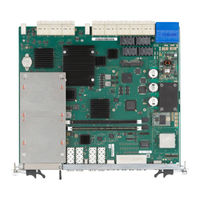
Artesyn ATCA-F125 Manual (138 pages)
Brand:
Artesyn
| Category:
Motherboard
| Size: 8 MB
Table of Contents
Table of Contents
3
About this Manual
11
Safety Notes
15
Sicherheitshinweise
23
Introduction
31
Features
31
Standard Compliances
32
Table 1-1 Standard Compliances
32
Figure 1-1 Declaration of Conformity
34
Mechanical Data
35
Ordering Information
35
Table 1-3 Blade Variants - Ordering Information
35
Blade Accessories
36
Table 1-4 Blade Accessories - Ordering Information
36
Product Identification
37
Figure 1-2 Serial Number Locater
37
Hardware Preparation and Installation
39
Overview
39
Unpacking and Inspecting the Blade
39
Requirements
40
Environmental Requirements
41
Table 2-1 Environmental Requirements
42
Thermal Requirements
43
Power Requirements
44
Table 2-2 Power Requirements
44
Rear Transition Modules
45
Blade Configuration
46
SATA Drive Installation
46
Blade Installation and Removal
46
Installing Blade
47
Removing Blade
50
AMC Module Installation and Removal
52
Installing and Removing SFP Modules
55
Installing an SFP Module
56
Removing an SFP Module
59
Controls, Leds, and Connectors
63
Overview
63
Blade Layout
63
Faceplate Leds
63
Figure 3-1 ATCA-F125 Face Plate
63
Reset Switch
65
Faceplate Connectors
65
Table
65
Table 3-2 Service Processor Ethernet RJ45 Connector Pin Assignment (J9)
65
Table 3-3 Service Processor Serial RS232 RJ45 Connector (J1)
65
Table 3-4 Service Processor USB Connector (J10)
66
Table 3-5 SFP+ Connectors Pin Assignment (J4-J7)
66
Table 3-6 Master/Slave Sync Connector (J12-U1)
67
Table 3-7 Inter-Shelf Connectors (J12-L1, L2, L3, U2, U3)
67
Table 3-8 T1/E1 Port Connectors (J12-L4 and J12-U4)
67
Backplane Connectors
68
Zone 1
68
Table
68
Table 3-9 Zone 1 Connector P1 Pin Assignment
68
Zone 2
69
Table 3-10 Connector P20 Pin Assignment
69
Table
69
Table 3-11 Connector P21 Pin Assignment
70
Table 3-12 Connector P22 Pin Assignment
70
Table 3-13 Connector P23 Pin Assignment
71
Table 3-14 Connector P24 Pin Assignment
71
Zone 3
72
Table 3-15 Connector P32 Pin Assignment
72
Table 3-16 Connector P30 Pin Assignment
72
Table 3-17 Connector P31 Pin Assignment
73
Table
73
Module Connectors
74
Figure 3-2 Module Connectors Location
74
AMC Connector
75
Table 3-18 J8 AMC Bay Connector Pin Assignment
75
SAS/SATA Connector
77
Embedded USB Connector
77
Table 3-19 J11 SAS/SATA Connector Pin Assignment
77
Table 3-20 P8 Eusb Header Pin Assignment
77
Table
77
Processor COP Header
78
Table 3-21 P50 COP Header Pin Assignment
78
H8S Console and Programming Header
79
Switches
79
Table 3-22 P9 H8S Console Header Pin Assignment
79
Functional Description
81
Block Diagram
81
Processor
82
Memory
83
Memory Interface
83
Memory Sockets
83
Memory Modules
83
Persistent Memory
84
Ipmi
85
Figure 4-2 IPMI Block Diagram
86
Temperature Sensors
87
Fpga
87
Table 4-1 Temperature Sensors
87
Serial Configuration PROM
88
Figure 4-3 FPGA SPI ROM Configuration
89
Boot and User Flashes
90
Boot Flash Backup Recovery
90
Figure 4-4 Boot PROM Backup Recovery
90
Base Channel Interface
91
Table 4-2 Boot PROM Backup Recovery Operation
91
Figure 4-5 Base Channel Block Diagram
92
Table 4-3 BCM56344 Base Channel Switch Connections
93
Base Channel Phys
94
Shmc Cross-Connect
95
Figure 4-6 Standard Shmc Cross-Connect
95
Table 4-4 Fabric Channel Switch Connections
96
Fabric Channel Block Diagram
96
Table
97
Table
98
SFP+ Module Status and Control Interface
99
Figure 4-9 AMC Bay Connection Diagram
101
Table 4-6 AMC Bay Port Assignments
102
Figure
103
Figure 4-11 Fabric Channel Cross Connect
104
4.11.1 Telecom Clocking Subsystem
106
Figure 4-13 BITS/SSU Clock Flow
108
Figure 4-14 Reset Structure Block Diagram
109
Reset Signals
110
Figure 4-15 AMC Enable Logic
112
Table 4-8 Interrupt Mapping
113
Table 5-1 Physical Address Map
122
Linux Devices
123
Table 5-3 POST Result Format
124
Table 5-4 Post Results in SYS FW PROGRESS IPMI Sensor Reading Data
124
Table 5-5 SYS FW PROGRESS IPMI Sensor - POST Error Event Codes
125
POST Routines
125
Table 5-7 Environment Variable Post_Control
127
Table 5-8 ATCA-F125 Specific U-Boot Commands
127
Table 5-9 ATCA-F125 Specific U-Boot Environment Variables
128
Table B-1 Artesyn Embedded Technologies - Embedded Computing Publications
135
Table B-2 Specifications
135
Advertisement
Artesyn ATCA-F125 Quick Start Manual (2 pages)
Brand:
Artesyn
| Category:
Server
| Size: 0 MB
Table of Contents
Quick Start Guide
1
Observe ESD-Safe Measures
1
What’s in the Box?
1
Prepare the Installation Site
1
Install the SATA Storage
1
Install the /QSFP+SFP+ Modules
1
Install the Pramc
1
Install the Blade
2
Install the Blade (Cont.)
2
Finding more Information
2
Technical Assistance
2
Advertisement
Related Products
Artesyn ATCA-7367
Artesyn ATCA-7480
Artesyn AXP 1410
Artesyn AXP640
Artesyn AXP1440
Artesyn ATCA-7370
Artesyn ATCA-7370-S
Artesyn ATCA-7360
Artesyn ATCA-7475
Artesyn ATCA-F140
Artesyn Categories
Motherboard
Server
Single board computers
PCI Card
Computer Hardware
More Artesyn Manuals
Login
Sign In
OR
Sign in with Facebook
Sign in with Google
Upload manual
Upload from disk
Upload from URL